Infiniti FX35 / FX45. Manual — part 710
FUEL LEVEL SENSOR UNIT, FUEL FILTER AND FUEL PUMP ASSEMBLY
FL-9
< SERVICE INFORMATION >
C
D
E
F
G
H
I
J
K
L
M
A
FL
N
P
O
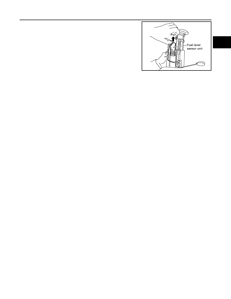
3.
After fixing tabs are disengaged, slide fuel level sensor unit out
in direction shown by the arrow.
CAUTION:
Do not disassemble fuel filter and fuel pump assembly.
ASSEMBLY
1.
Check for damage of fuel level sensor unit installation position on the side of fuel filter and fuel pump
assembly.
2.
Slide fuel level sensor unit until it aligns to installation groove, then insert it until stop.
• After inserting, apply force in reverse direction (removal direction) to ensure it cannot be pulled out.
3.
Connect harness connector.
• Securely insert harness connector until it stops.
PBIC1080E
FL-10
< SERVICE INFORMATION >
FUEL TANK
FUEL TANK
Component
INFOID:0000000001327110
Removal and Installation
INFOID:0000000001327111
REMOVAL
WARNING:
Be sure to read “General Precautions” when working on the fuel system. Refer to
.
• Drain fuel from fuel tank if necessary. Refer to
FL-4, "Removal and Installation"
.
• Perform work on level place.
1.
Perform steps 2 to 7 of “REMOVAL” in “ FUEL LEVEL SENSOR UNIT, FUEL FILTER AND FUEL PUMP
ASSEMBLY” on main and sub fuel level sensor units. Refer to
FL-4, "Removal and Installation"
.
2.
Remove tunnel stay. Refer to
RSU-5, "On-Vehicle Inspection and Service"
.
3.
Remove exhaust front tube, center muffler and main muffler. Refer to
EX-3, "Checking Exhaust System"
.
4.
Remove insulator.
5.
Remove propeller shaft. Refer to
.
6.
Remove parking rear brake cables. Refer to
7.
Compress coil spring and remove coil spring.
8.
Remove rear suspension assembly.
9.
Remove fuel tank protector.
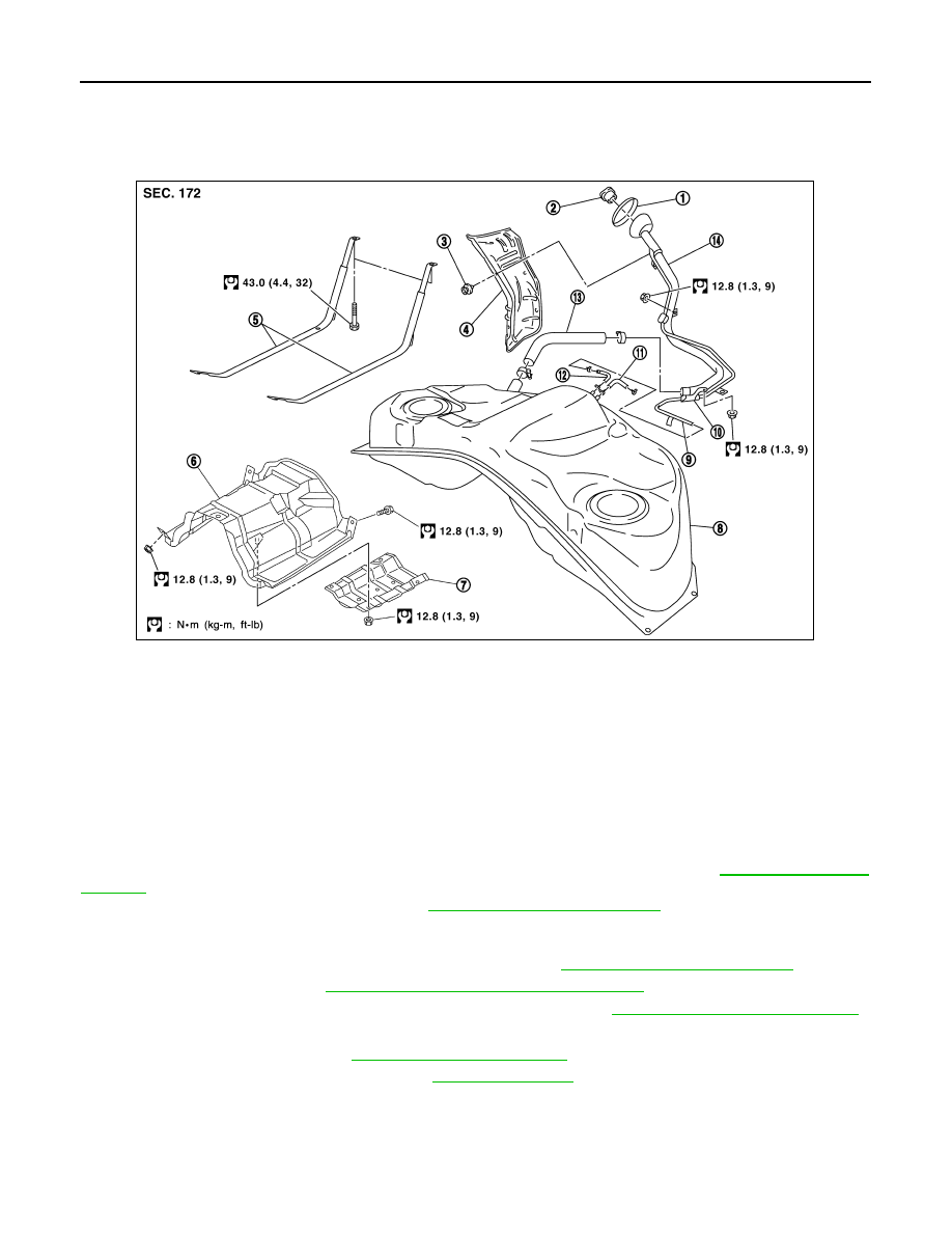
1.
Grommet
2.
Fuel filler cap
3.
Clip
4.
Fuel filler tube protector
5.
Fuel tank mounting band
6.
Fuel tank protector
7.
Insulator
8.
Fuel tank
9.
Vent tube
10. Vent hose
11.
EVAP hose
12. Vent hose
13. Fuel filler hose
14.
Fuel filler tube
PBIC1580E
FUEL TANK
FL-11
< SERVICE INFORMATION >
C
D
E
F
G
H
I
J
K
L
M
A
FL
N
P
O
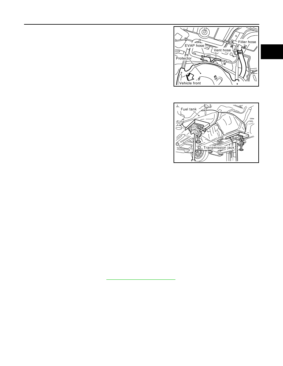
10. Disconnect fuel filler hose, vent hose and EVAP hoses at fuel
tank side.
11. Support the lower part of fuel tank with transmission jack.
CAUTION:
Support the position that fuel tank mounting bands do not
engage.
12. Remove fuel tank mounting bands.
13. Supporting with hands, descend transmission jack carefully, and remove fuel tank.
CAUTION:
• Make sure that all connection points have been disconnected.
• Confirm there is no interference with vehicle.
14. Remove fuel filler tube protector and fuel filler tube, if necessary.
INSTALLATION
Note the following, and install in the reverse order of removal.
• Surely clamp fuel hoses and insert hose to the length below.
• Be sure hose clamp is not placed on swelled area of fuel tube.
• Tighten fuel hose clamp so that the distance between its lugs becomes to the following.
• To connect quick connector, refer to
FL-4, "Removal and Installation"
INSPECTION AFTER INSTALLATION
Use the following procedure to check for fuel leaks.
1.
Turn ignition switch “ON” (with engine stopped), and check connections for leakage by applying fuel pres-
sure to fuel piping.
2.
Start engine and rev it up and make sure there are no fuel leaks at the fuel system tube and hose connec-
tions.
PBIC1581E
PBIC0878E
Fuel filler hose
: 35 mm (1.38 in)
The other hoses
: 25 mm (0.98 in)
Fuel tank side
: 8 - 12 mm (0.31 - 0.47 in)
Fuel filler tube side
: 5.7 - 9.7 mm (0.224 - 0.382 in)

FL-12
< SERVICE INFORMATION >
SERVICE DATA AND SPECIFICATIONS (SDS)
SERVICE DATA AND SPECIFICATIONS (SDS)
Standard and Limit
INFOID:0000000001327112
FUEL TANK
Unit: US gal, Imp gal
Fuel tank capacity
Approx. 90 (23-3/4, 19-3/4)
Fuel recommendation
Refer to
Нет комментариевНе стесняйтесь поделиться с нами вашим ценным мнением.
Текст