Infiniti FX35 / FX45. Manual — part 99
AT-324
< SERVICE INFORMATION >
ASSEMBLY
5.
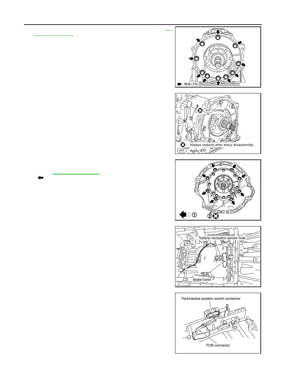
Tighten oil pump mounting bolts to specified torque. Refer to
.
CAUTION:
Apply ATF to oil pump bushing.
6.
Install O-ring to input clutch assembly.
CAUTION:
• Do not reuse O-ring.
• Apply ATF to O-ring.
7.
Install converter housing to transmission case, and then tighten
converter housing mounting bolts (1) to the specified torque.
Refer to
•
: Bolt (8)
CAUTION:
Do not reuse self-sealing bolt (2).
8.
Make sure that brake band does not close turbine revolution
sensor hole.
9.
Install control valve with TCM.
a.
Connect TCM connector and park/neutral position switch con-
nector.
SCIA2300E
SCIA5011E
SCIA7985E
SCIA5034E
SCIA5449E
ASSEMBLY
AT-325
< SERVICE INFORMATION >
D
E
F
G
H
I
J
K
L
M
A
B
AT
N
O
P
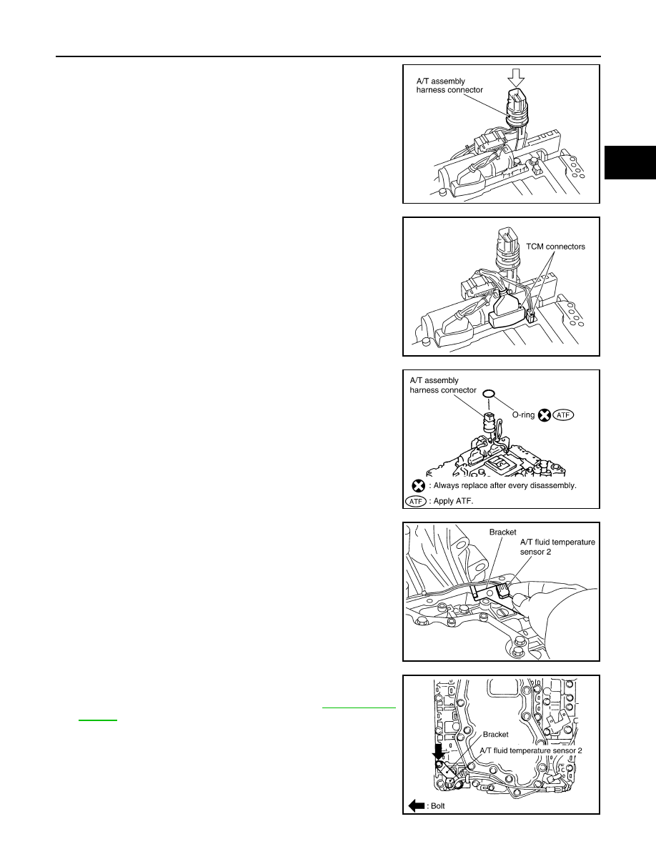
b.
Install A/T assembly harness connector from control valve with
TCM.
c.
Connect TCM connectors.
d.
Install O-ring to A/T assembly harness connector.
CAUTION:
• Do not reuse O-ring.
• Apply ATF to O-ring.
e.
Install A/T fluid temperature sensor 2 to bracket.
f.
Install A/T fluid temperature sensor 2 (with bracket) in control
valve with TCM, and then tighten A/T fluid temperature sensor 2
mounting bolts to the specified torque. Refer to
CAUTION:
Adjust bolt hole of bracket to bolt hole of control valve.
SCIA5450E
SCIA5447E
SCIA5155E
SCIA5264E
SCIA5301E

AT-326
< SERVICE INFORMATION >
ASSEMBLY
g.
Install control valve with TCM in transmission case.
CAUTION:
• Make sure that turbine revolution sensor securely installs
turbine revolution sensor hole.
• Hang down revolution sensor harness toward outside so
as not to disturb installation of control valve with TCM.
• Adjust A/T assembly harness connector of control valve
with TCM to terminal hole of transmission case.
• Assemble it so that manual valve cutout is engaged with
manual plate projection.
h.
Install bolts A, B and C to control valve with TCM.
•
: Front
i.
Tighten bolt 1, 2 and 3 temporarily to prevent dislocation. After
that tighten them in order (1
→
2
→
3), and then tighten other
bolts to the specified torque. Refer to
.
•
: Front
SCIA5034E
SCIA5035E
Bolt symbol
Length mm (in)
Number of bolts
A
42 (1.65)
5
B
55 (2.17)
6
C
40 (1.57)
1
SCIA8077E
SCIA8078E
ASSEMBLY
AT-327
< SERVICE INFORMATION >
D
E
F
G
H
I
J
K
L
M
A
B
AT
N
O
P
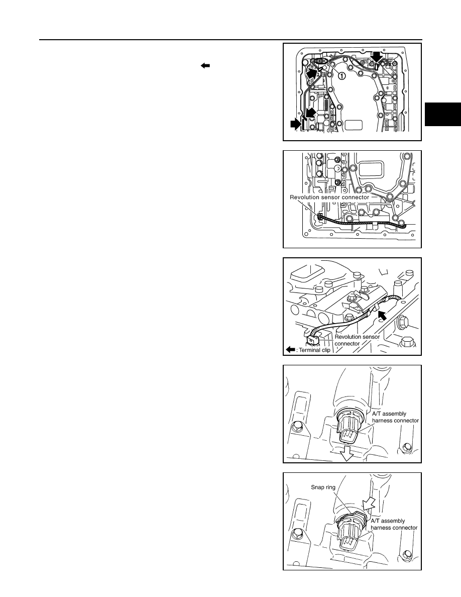
10. Connect A/T fluid temperature sensor 2 connector (1).
11. Securely fasten terminal cord assembly and A/T fluid tempera-
ture sensor 2 harness with terminal clips (
).
12. Connect revolution sensor connector.
13. Securely fasten revolution sensor 2 harness with terminal clip.
14. Pull down A/T assembly harness connector.
CAUTION:
Be careful not to damage connector.
15. Install snap ring to A/T assembly harness connector.
SCIA8069E
SCIA7524E
SCIA7526E
SCIA5299E
SCIA5300E
Нет комментариевНе стесняйтесь поделиться с нами вашим ценным мнением.
Текст