Infiniti FX35 / FX45. Manual — part 251
FRONT DISC BRAKE
BR-21
< SERVICE INFORMATION >
C
D
E
G
H
I
J
K
L
M
A
B
BR
N
O
P
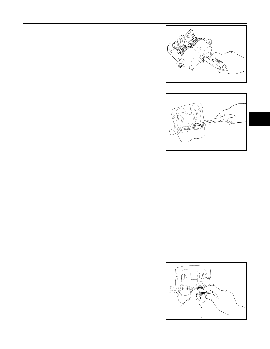
3.
Remove sliding pins and sliding pin boots from torque member.
4.
Place a wooden block as shown in the figure, and blow air from
union bolt mounting hole to remove pistons and piston boots.
CAUTION:
Do not get your fingers caught in piston.
5.
Using a flat-bladed screwdriver, remove piston seal from cylin-
der body.
CAUTION:
Be careful not to damage cylinder inner wall.
INSPECTION AFTER DISASSEMBLY
Cylinder Body
CAUTION:
Use new brake fluid to clean. Do not use mineral oils such as gasoline or kerosene.
• Check the inner wall of cylinder for corrosion, wear, and damage. If a malfunction is detected, replace cylin-
der body.
• Minor flaws caused by corrosion or a foreign material can be removed by polishing a surface of the inner
wall with a fine sandpaper. Replace cylinder body, if necessary.
Torque Member
Check for wear, cracks, and damage. If a malfunction is detected, replace the torque member.
Piston
CAUTION:
The piston sliding surface is plated. Do not polish with sandpaper.
Check piston surface for corrosion, wear, and damage. If a malfunction is detected, replace applicable part.
Sliding Pin, Sliding Pin Bolt, and Sliding Pin Boot
Check sliding pins, sliding pin bolts and sliding pin boots for wear, damage, and cracks. If a malfunction is
detected, replace applicable part.
ASSEMBLY
1.
Apply polyglycol ether based lubricant to the piston seal, and
install them to the cylinder body.
CAUTION:
Do not reuse piston seal.
BRB0032D
SFIA0141E
SFIA2920E
BR-22
< SERVICE INFORMATION >
FRONT DISC BRAKE
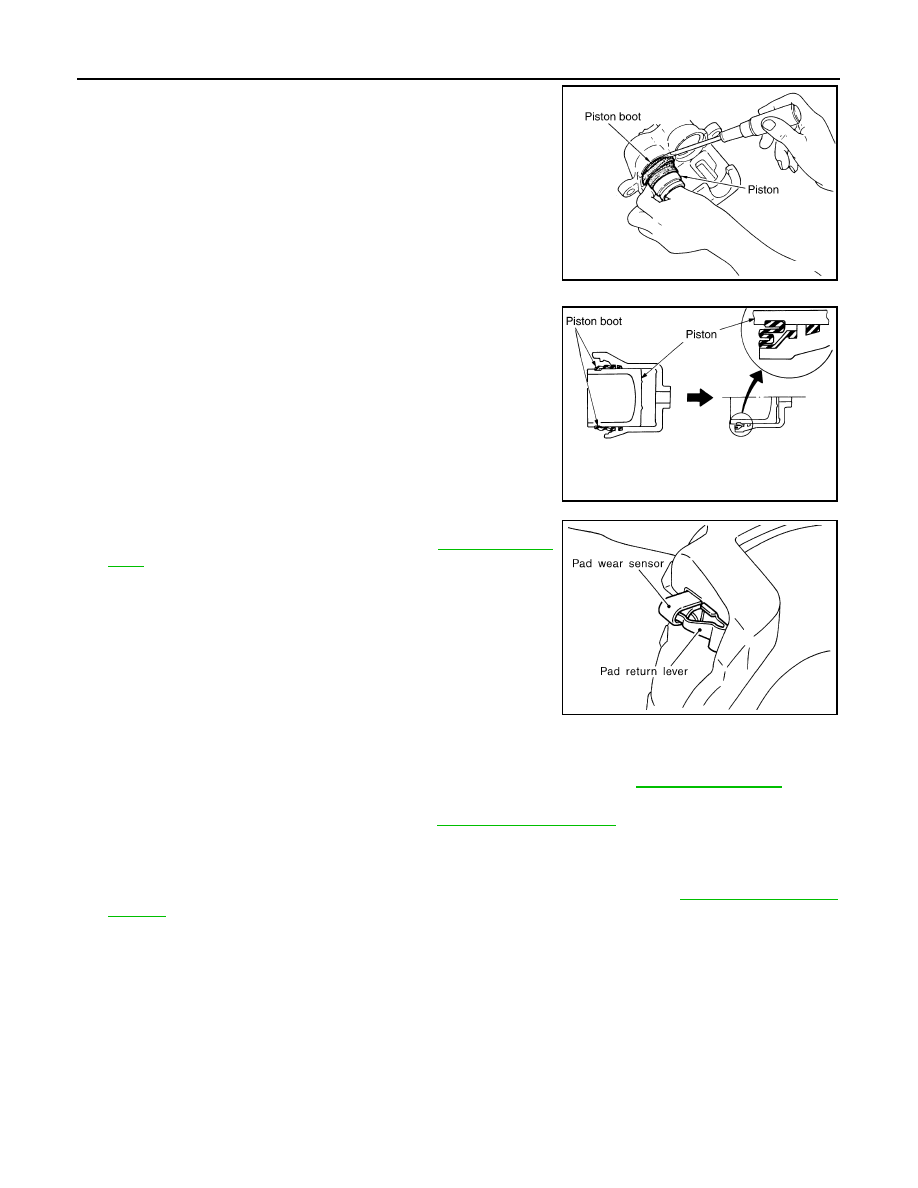
2.
Apply rubber grease to piston boot. Cover the piston end with
piston boot, and install cylinder side lip on piston boot properly
into groove on cylinder body.
CAUTION:
Do not reuse piston boot.
3.
Apply brake fluid to piston, and press piston into cylinder body
by hand to assemble piston side lip on piston boot properly into
groove on piston.
CAUTION:
Press piston evenly and vary the pressing point to prevent
cylinder inner wall from being rubbed.
4.
Install sliding pins and sliding pin boots to torque member.
5.
Install the torque member to the knuckle spindle and tighten the
mounting bolts to the specified torque. Refer to
.
CAUTION:
Before installing torque member to vehicle, wipe oil and
grease on the washer seats on steering knuckle and the
mounting surface of the torque member.
6.
Install pad retainers to torque member.
7.
After assembling shims and shim covers to pad, install it to
torque member.
CAUTION:
Inner pad and outer pad have pad-return mechanism on the
upper side of the pad retainer. When installing pad, be sure to install pad return lever to pad wear
sensor securely as shown in the figure.
8.
Install cylinder body, and tighten sliding pin bolt to specified torque. Refer to
9.
Install a projection of brake hose metal fitting by aligning with protrusions on cylinder body, and then
tighten union bolts to specified torque. Refer to
CAUTION:
• Assemble brake hose securely to protrusions on cylinder body.
• Do not reuse copper washer for union bolts.
10. After installing caliper assembly, refill with new brake fluid and bleed air. Refer to
DISC ROTOR INSPECTION
Visual Inspection
Check surface of disc rotor for uneven wear, cracks, and serious damage. If any of them is detected, replace
applicable part.
Runout Inspection
1.
Using wheel nuts, fix disc rotor to wheels hub. (2 or more positions)
SFIA2432E
SFIA2279E
SBR557E
FRONT DISC BRAKE
BR-23
< SERVICE INFORMATION >
C
D
E
G
H
I
J
K
L
M
A
B
BR
N
O
P
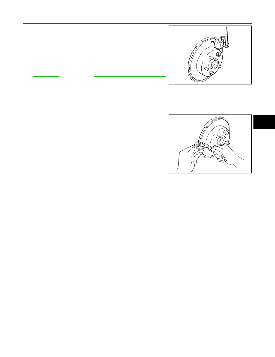
2.
Using a dial indicator, check runout.
CAUTION:
Before measuring, make sure that wheel bearing axle end
play is within the specification. Refer to
FAX-11, "On-Vehicle Inspection"
(AWD models).
3.
If runout is outside the limit, find the minimum runout point by
shifting the mounting positions of disc rotor and wheel hub by one hole.
4.
If runout is still outside the limit after performing the above operation, replace or lathe the disc rotor.
[When lathing, use the Pro-Cut PFM On-Car Brake Lathe (Tool No, 38-PFM90.5) or equivalent.]
Thickness Inspection
Using a micrometer, check thickness of disc rotor. If thickness is out-
side the specification, replace disc rotor.
Brake Burnishing Procedure
INFOID:0000000001327632
Burnish brake pad contact surfaces of disc rotor according to following procedure after refinishing or replacing
drums or rotors, after replacing pads or linings, or if a soft pedal occurs at very low mileage.
CAUTION:
• Be careful of vehicle speed because brake does not operate easily until pad and disc rotor are
securely fitted.
• Only perform this procedure under safe road and traffic conditions. Use extreme caution.
1.
Drive vehicle on straight, flat road.
2.
Depress brake pedal with the power to stop vehicle within 3 to 5 seconds until the vehicle stops.
3.
Drive without depressing brake for a few minutes to cool brake.
4.
Repeat steps 1 to 3 until pad and disc rotor are securely fitted.
Measurement point
: At a point 10.0 mm (0.394 in)
from outer edge of disc.
Runout limit
: 0.04 mm (0.0016 in) or less
SBR019B
Standard thickness
: 34.0 mm (1.339 in)
Wear limit
: 32.0 mm (1.260 in)
Maximum uneven wear
(measured at 8 positions)
: 0.015 mm (0.0006 in)
or less
SBR020B
BR-24
< SERVICE INFORMATION >
REAR DISC BRAKE
REAR DISC BRAKE
On-Vehicle Inspection
INFOID:0000000001327633
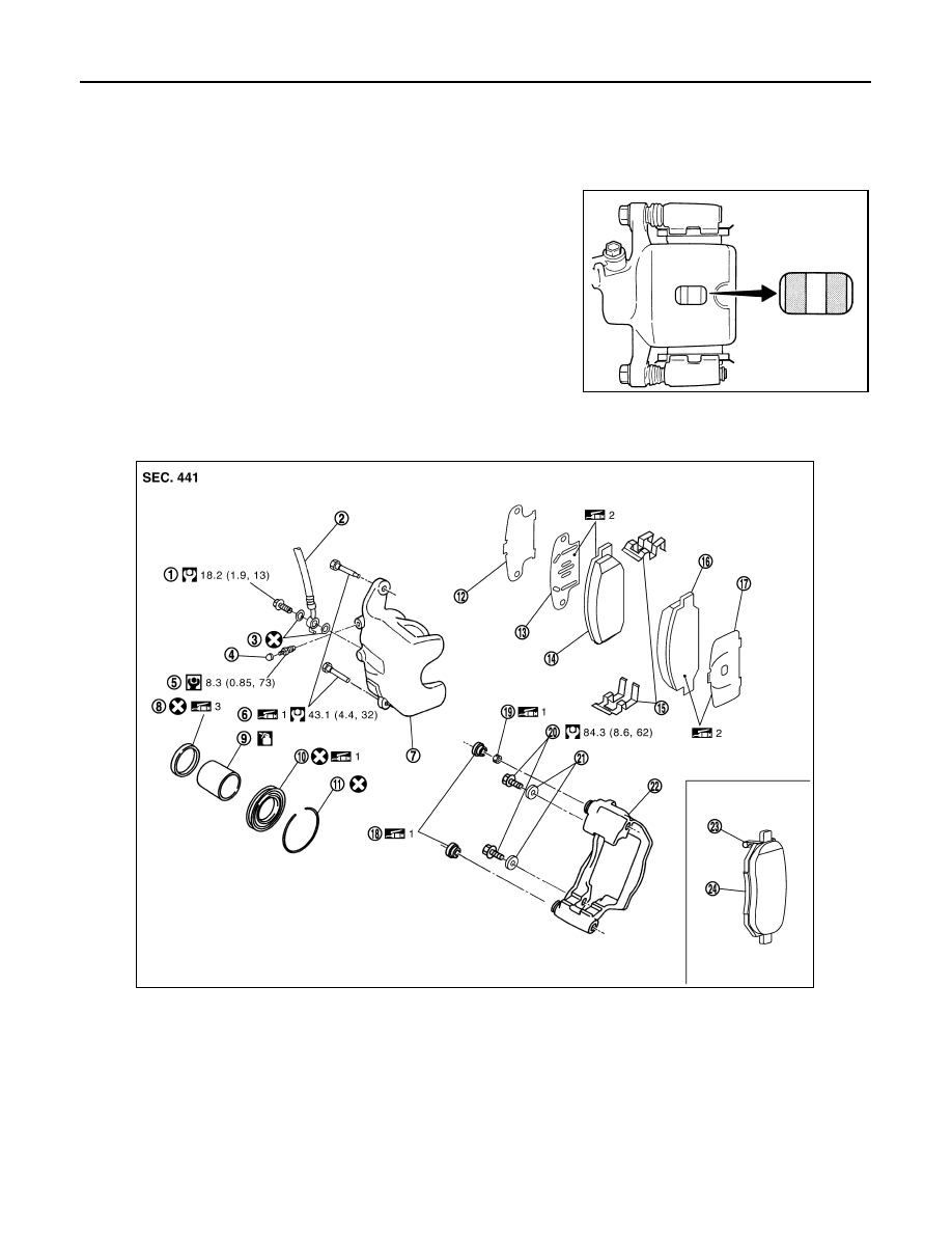
PAD WEAR INSPECTION
• Check the thickness from check hole on cylinder body. Use a scale
for inspection if necessary.
Component
INFOID:0000000001327634
Standard thickness
: 8.5 mm (0.335 in)
Repair limit thickness
: 2.0 mm (0.079 in)
BRA0010D
1.
Union bolt
2.
Brake hose
3.
Copper washer
4.
Cap
5.
Bleed valve
6.
Sliding pin bolt
7.
Cylinder body
8.
Piston seal
9.
Piston
10.
Piston boot
11. Retaining ring
12. Inner shim cover
13.
Inner shim
14. Inner pad
15. Pad retainer
16.
Outer pad
17. Outer shim
18. Sliding pin boot
19.
Bushing
20. Torque member mounting bolt
21. Washer
22.
Torque member
23. Pad wear sensor
24. Inner pad (RH)
PFIA0808J
Нет комментариевНе стесняйтесь поделиться с нами вашим ценным мнением.
Текст