Infiniti FX35 / FX45. Manual — part 249
BRAKE MASTER CYLINDER
BR-13
< SERVICE INFORMATION >
C
D
E
G
H
I
J
K
L
M
A
B
BR
N
O
P
5.
Remove master cylinder assembly mounting nut, remove master cylinder assembly from the vehicle.
Refer to
BR-14, "Removal and Installation"
.
INSTALLATION
CAUTION:
• Refill with new brake fluid “DOT3”.
• Do not reuse drained brake fluid.
1.
Install in the reverse order of removal, and tighten mounting nuts to the specified torque. Refer to
.
2.
Refill brake fluid and bleed air. Refer to
Disassembly and Assembly
INFOID:0000000001327620
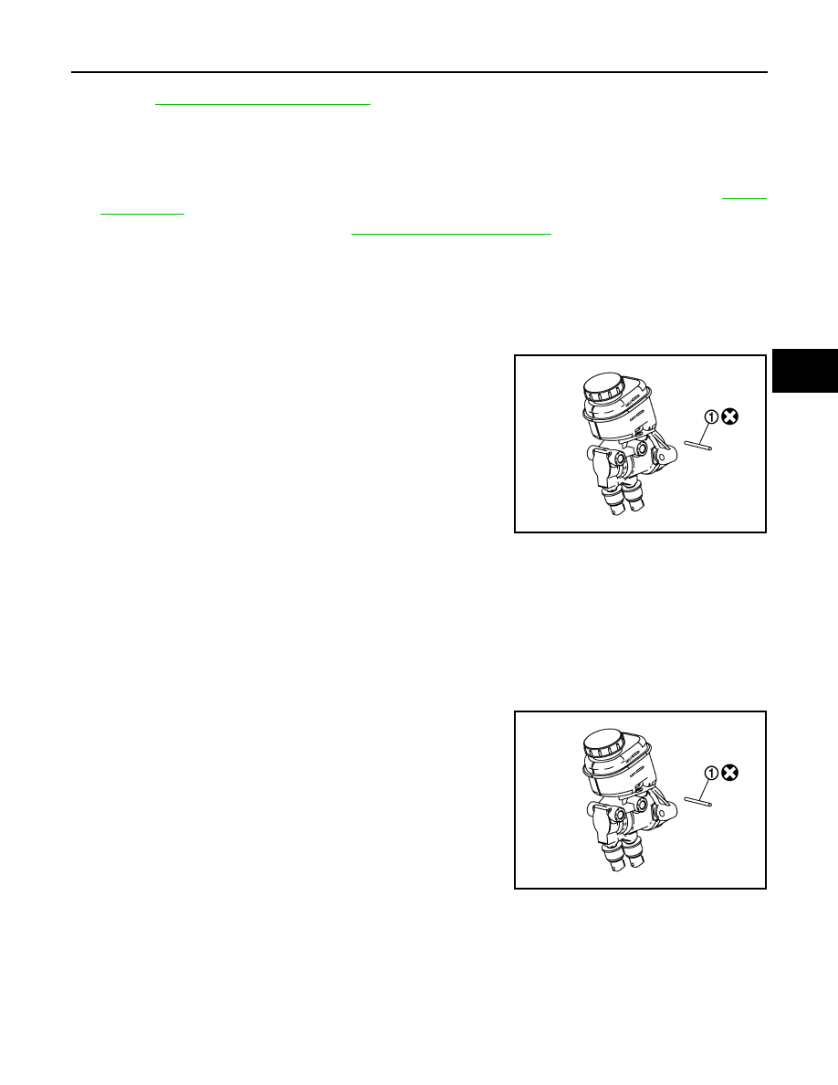
DISASSEMBLY
CAUTION:
• Master cylinder can not be disassembled.
• Remove reservoir tank only when absolutely necessary.
1.
Remove pin (1).
2.
Remove reservoir tank and grommet from master cylinder
assembly.
ASSEMBLY
CAUTION:
• Do not use mineral oil such as kerosene, gasoline during the cleaning and assembly process.
• Do not drop parts. If a part is dropped, do not use it.
1.
Apply brake fluid grommet and attach to master cylinder assembly.
CAUTION:
Do not reuse grommet.
Do not reuse pin.
2.
Install reservoir tank onto master cylinder assembly.
3.
Install pin (1).
PFIA0816E
PFIA0816E

BR-14
< SERVICE INFORMATION >
BRAKE BOOSTER
BRAKE BOOSTER
On-Vehicle Service
INFOID:0000000001327621
OPERATING CHECK
With engine stopped, change the vacuum to the atmospheric pres-
sure by depressing brake pedal several times. Then with brake
pedal fully depressed, start engine and when the vacuum pressure
reaches the standard, make sure the clearance between brake pedal
and floor panel decreases.
CAUTION:
Depressing pedal interval is approximately 5 seconds.
AIRTIGHT CHECK
• Run engine at idle for approximately 1 minute, and stop it after
applying vacuum to booster. Depress brake pedal normally to
change the vacuum to the atmospheric pressure. Make sure dis-
tance between brake pedal and floor panel gradually increases.
• Depress brake pedal while engine is running, and stop engine with
pedal depressed. The pedal stroke should not change after holding
pedal down for 30 seconds.
CAUTION:
Depressing brake pedal is interval is approximately at intervals
5 seconds.
Component
INFOID:0000000001327622
Removal and Installation
INFOID:0000000001327623
REMOVAL
BRA0037D
SBR365AA
1.
Reservoir tank
2.
Master cylinder
3.
Gasket
4.
Brake booster
Refer to
, for the symbols in the figure.
PFIA0817E

BRAKE BOOSTER
BR-15
< SERVICE INFORMATION >
C
D
E
G
H
I
J
K
L
M
A
B
BR
N
O
P
CAUTION:
• Be careful not to splash brake fluid on painted areas; it may cause paint damage. If brake fluid is
splashed on painted surfaces of body, immediately wipe it off and them wash it away with water
immediately.
• Be careful not to deform or bend brake tube while removing and installing brake booster.
• Replace clevis pin if it is damaged.
• Be careful not to damage brake booster stud bolt threads. If brake booster is tilted or inclined during
installation, dash panel may damage the threads.
• Install the check valve in the correct direction.
1.
Remove vacuum hose from brake booster. Refer to
2.
Remove brake master cylinder. Refer to
BR-12, "Removal and Installation"
3.
Disconnect harness connector from brake booster assembly. (ICC model)
4.
Remove snap pin and clevis pin from inside the vehicle. Refer to
5.
Remove nuts from brake booster and brake pedal bracket.
6.
Remove brake booster assembly from engine room.
INSPECTION AFTER REMOVAL
Output Rod Length Inspection
1.
Using a handy vacuum pump, apply a vacuum of –66.7 kPa (–
500 mmHg, –19.69 inHg) to brake booster.
2.
Check output rod length.
INSTALLATION
1.
Loosen lock nut to adjust input rod length so that the length “B”
(shown in the figure) satisfies the specified value.
2.
After adjusting “B”, temporarily tighten lock nut to install brake
booster assembly to the vehicle. At this time, make sure to
install a gasket between brake booster assembly and the engine
room.
3.
Connect brake pedal with clevis of input rod.
4.
Install brake pedal bracket mounting nuts and bolt and tighten
them to the specified torque.
5.
Install brake tube from brake master cylinder to ABS actuator. Refer to
6.
Install master cylinder to booster assembly. Refer to
BR-12, "Removal and Installation"
.
7.
Adjust the height and play of brake pedal.
BR-5, "Inspection and Adjustment"
8.
Tighten lock nut of input rod to the specified torque. Refer to
.
9.
Bleed air. Refer to
Standard dimension when applying a vacuum of
−
66.7 kPa (
−
500 mmHg,
−
19.69 inHg):
15.6
−
15.9 mm (0.614
−
0.626 in)
SFIA2146E
Length “B”
: 126.5 mm (4.98 in)
SGIA0060E
BR-16
< SERVICE INFORMATION >
VACUUM LINES
VACUUM LINES
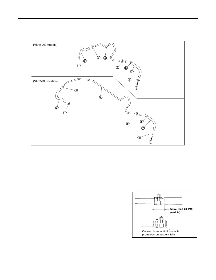
Component
INFOID:0000000001327624
Removal and Installation
INFOID:0000000001327625
CAUTION:
• Because vacuum hose contains a check valve, it must be installed in the correct direction. Refer to
the stamp or label to confirm correct installation. The brake booster will not operate normally if hose
is installed in the wrong direction.
• Insert vacuum hose for at least 24 mm (0.94 in).
• Do not use lubricating oil during assembly.
Inspection
INFOID:0000000001327626
VISUAL INSPECTION
Check for improper assembly, damage and deterioration.
CHECK VALVE INSPECTION
1.
Clamp
2.
Vacuum hose
3.
Clamp
4.
Vacuum piping
5.
Clamp
6.
Engine direction indicator
7.
Vacuum hose (Build in check valve)
8.
Clamp
9.
Brake booster
SFIA1134E
SBR225B
Нет комментариевНе стесняйтесь поделиться с нами вашим ценным мнением.
Текст