Infiniti FX35 / FX45. Manual — part 975

WW-22
< SERVICE INFORMATION >
FRONT WIPER AND WASHER SYSTEM
Displayed self-diagnosis results
NO DTC>>Replace BCM. Refer to
BCS-13, "Removal and Installation of BCM"
.
CAN COMM CIRCUIT>>Check CAN communication line of BCM. Refer to
LAN-43, "CAN System Specifica-
Front Wiper Intermittent Operation Switch Position Cannot Be Adjusted
INFOID:0000000001328560
1.
CHECK CIRCUIT BETWEEN COMBINATION SWITCH AND BCM
With CONSULT-III
1.
Select “INT VOLUME” of BCM data monitor item.
2.
Check that “INT VOLUME”, changes in order form 1 to 7 according to wiper switch operation.
Without CONSULT-III
LT-104, "Combination Switch Inspection"
OK or NG
OK
>> Replace BCM. Refer to
BCS-13, "Removal and Installation of BCM"
.
NG
>> Check combination switch (wiper switch). Refer to
LT-104, "Combination Switch Inspection"
.
Wiper Does Not Wipe When Front Washer Operates
INFOID:0000000001328561
1.
CHECK CIRCUIT BETWEEN COMBINATION SWITCH AND BCM
With CONSULT-III
1.
Select “FR WASHER SW” of BCM data monitor item.
2.
Check that “FR WASHER SW” turn ON-OFF according to front wiper switch operation.
Without CONSULT-III
LT-104, "Combination Switch Inspection"
OK or NG
OK
>> Replace BCM Refer to
BCS-13, "Removal and Installation of BCM"
NG
>> Check combination switch (wiper switch). Refer to
LT-104, "Combination Switch Inspection"
.
After Front Wiper Operate for 10 Seconds, They Stop for 20 Seconds, and After Re-
peating the Operation Five Times, They Become Inoperative
INFOID:0000000001328562
CAUTION:
• When auto-stop signal has not varied for 10 seconds or longer while IPDM E/R is operating front wip-
ers, IPDM E/R considers that front wipers are locked, and stops wiper output. That causes this symp-
tom.
• This status can be checked by “DATA MONITOR” of “IPDM E/R” on which “WIPER PROTECTION”
item shows “BLOCK”.
1.
CHECK WIPER MOTOR SIGNAL
With CONSULT-III
1.
Select “WIP AUTO STOP” of BCM data monitor item.
2.
Check that “WIP AUTO STOP” turns “ACT P” - “STOP P” linked with wiper operation.
Without CONSULT-III
GO TO 2.
OK or NG
OK
>> Replace IPDM E/R.
NG
>> GO TO 2.
2.
CHECK WIPER AUTO STOP CIRCUIT
1.
Turn ignition switch OFF.
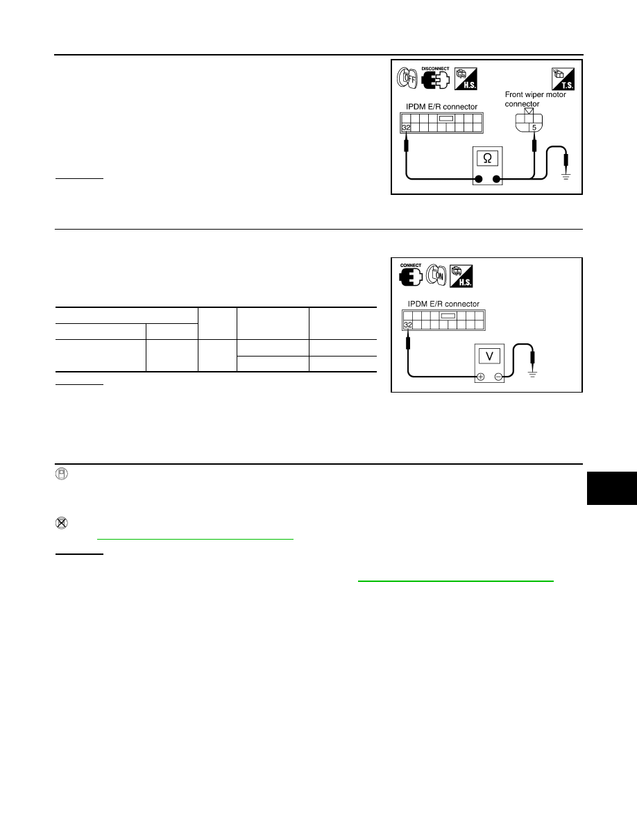
2.
Disconnect IPDM E/R connector and front wiper motor connector.
FRONT WIPER AND WASHER SYSTEM
WW-23
< SERVICE INFORMATION >
C
D
E
F
G
H
I
J
L
M
A
B
WW
N
O
P
3.
Check continuity between IPDM E/R harness connector and
front wiper motor harness connector.
4.
Check continuity between IPDM E/R harness connector and
ground.
OK or NG
OK
>> GO TO 3.
NG
>> Repair harness or connector.
3.
CHECK FRONT WIPER MOTOR
1.
Connect IPDM E/R connector and front wiper connector.
2.
Turn ignition switch ON.
3.
Check voltage between IPDM E/R harness connector and
ground while front wiper motor is stopped and while it is operat-
ing.
OK or NG
OK
>> Replace IPDM E/R.
NG
>> Replace front wiper motor.
Front Wiper Does Not Stop
INFOID:0000000001328563
1.
CHECK CIRCUIT BETWEEN COMBINATION SWITCH AND BCM
With CONSULT-III
1.
Select “FR WIPER INT”, “FR WIPER LOW”, “FR WIPER HI”, and “FR WASHER SW” of BCM data moni-
tor item.
2.
With operating the wiper switch, check the monitor status.
Without CONSULT-III
LT-104, "Combination Switch Inspection"
OK or NG
OK
>> Replace IPDM E/R.
NG
>> Check combination switch (wiper switch). Refer to
LT-104, "Combination Switch Inspection"
.
Removal and Installation of Front Wiper Arms, Adjustment of Wiper Arms Stop Loca-
tion
INFOID:0000000001328564
REMOVAL
1.
Turn front wiper switch ON to operate wiper motor, and then turn front wiper switch OFF (auto stop).
2.
Open hood, remove front wiper arm caps, and remove washer tube from washer tube joint.
3.
Remove front wiper arm nuts.
4.
Raise front wiper arms, and remove front wiper arms from the vehicle.
INSTALLATION
32 – 5
: Continuity should exist.
32 – Ground
: Continuity should not exist.
PKIA5195E
(+)
(-)
Condition
Voltage
(Approx.)
IPDM E/R connector
Terminal
E7
32
Ground
Wiper stopped
0 V
Wiper operating
Battery voltage
PKIA5196E

WW-24
< SERVICE INFORMATION >
FRONT WIPER AND WASHER SYSTEM
1.
Clean up the pivot area as shown in the figure. This will reduce
possibility of front wiper arm nuts looseness.
2.
Prior to front wiper arms installation, turn front wiper switch ON
to operate wiper motor, and then turn front wiper switch OFF
(auto stop).
3.
Install washer tube to washer tube joint.
4.
Lift the blade up and then set it down onto windshield glass sur-
face to set the blade center to clearance “L1” & “L2” immedi-
ately.
5.
Tighten front wiper arm nuts to specified torque.
6.
Spray washer fluid. Turn on wiper switch ON to operate wiper
motor, and then turn front wiper switch OFF (auto stop).
7.
Make sure that wiper blades stop within clearance “L1” & “L2”.
8.
Install front wiper arm caps.
Removal and Installation of Front Wiper Drive Assembly
INFOID:0000000001328565
REMOVAL
1.
Remove front wiper arms. Refer to
WW-23, "Removal and Installation of Front Wiper Arms, Adjustment of
.
2.
Remove cowl top cover. Refer to
EI-23, "Component Parts Location"
.
3.
Remove washer tube.
4.
Disconnect wiper motor connector.
5.
Remove front wiper drive assembly mounting bolts, and remove
front wiper drive assembly from the vehicle.
INSTALLATION
1.
Install front wiper drive assembly to the vehicle.
2.
Connect wiper motor connector. Turn front wiper switch ON to operate wiper motor, and then turn front
wiper switch OFF (auto stop).
3.
Install washer tube to washer tube joint.
4.
Install cowl top cover. Refer to
EI-23, "Component Parts Location"
SEL024J
Front wiper arm nuts
: 23.6 N·m (2.4 kg-m, 17 ft-lb)
Clearance “L1”
: 49.4
±
5.0 mm (1.945
±
0.2 in)
Clearance “L2”
: 43.0
±
5.0 mm (1.693
±
0.2 in)
PKIA9951E
SKIA5070E
Front wiper drive assembly mounting bolt
: 4.5 N·m (0.46 kg-m, 40 in-lb)
FRONT WIPER AND WASHER SYSTEM
WW-25
< SERVICE INFORMATION >
C
D
E
F
G
H
I
J
L
M
A
B
WW
N
O
P
5.
Install front wiper arms and arm caps. Refer to
WW-23, "Removal and Installation of Front Wiper Arms,
Adjustment of Wiper Arms Stop Location"
.
6.
Install front wiper arm washer tube.
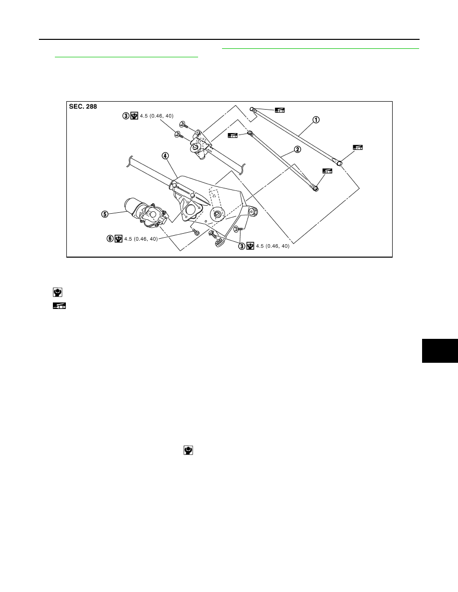
Disassembly and Assembly of Front Wiper Drive Assembly
INFOID:0000000001328566
DISASSEMBLY
1.
Remove wiper linkages from wiper motor and motor frame.
2.
Remove wiper motor mounting bolts, and remove wiper motor from wiper motor mounting frame.
CAUTION:
Be careful not to bend wiper linkages and not to damage the resin part of ball joint when removing
wiper linkages.
ASSEMBLY
1.
Connect wiper motor connector. Turn front wiper switch ON to operate wiper motor, and then turn front
wiper switch OFF (auto stop).
2.
Disconnect wiper motor connector.
3.
Install wiper motor to wiper motor mounting frame.
4.
Install wiper linkages to wiper frame and wiper motor.
CAUTION:
• Never drop the wiper motor or cause it to interfere with other parts.
• Check joint of motor arm and wiper linkages (at retainer) for grease conditions. Apply grease if nec-
essary.
Washer Nozzle Adjustment
INFOID:0000000001328567
1.
When wiper blade position is in auto stop condition, remove wiper motor connector to ensure wiper arms
do not move.
2.
Adjust each nozzle position (A, B, E, G, H, and K) so that spray positions are in the range of shaded parts.
CAUTION:
1.
Wiper linkage 2
2.
Wiper linkage 1
3.
Wiper motor frame mounting bolt
4.
Wiper motor mounting frame
5.
Wiper motor
6.
Wiper motor mounting bolt
: N·m (kg-m, in-lb)
: Should be lubricated with grease.
PKIC9716E
Wiper motor mounting bolts
:4.5 N·m (0.46 kg-m, 40 in-lb)
Нет комментариевНе стесняйтесь поделиться с нами вашим ценным мнением.
Текст