Infiniti FX35 / FX45. Manual — part 763
TROUBLE DIAGNOSES WORK FLOW
LAN-29
< SERVICE INFORMATION >
[CAN FUNDAMENTAL]
C
D
E
F
G
H
I
J
L
M
A
B
LAN
N
O
P
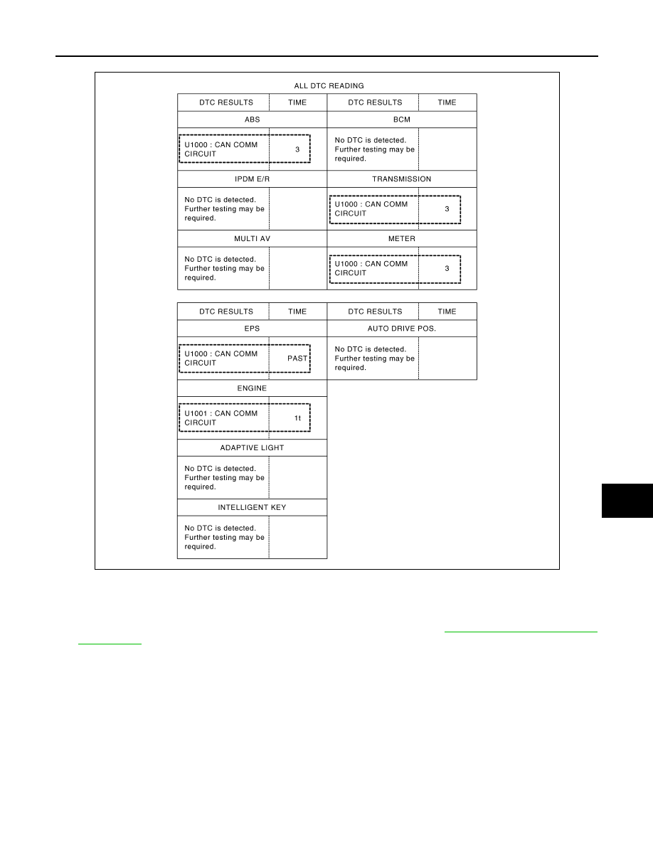
1.
SELF-DIAG RESULTS: Inspect the control units indicating “U1000” or “U1001” on SELF-DIAG RESULTS.
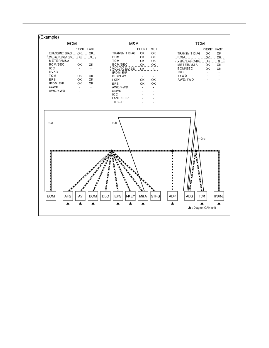
2.
CAN DIAG SUPPORT MNTR (with PAST): Check the CAN DIAG SUPPORT MNTR (with PAST) of units
indicating “U1000” or “U1001” on SELF-DIAG RESULTS. Draw a line on the diagnosis sheet to indicate
the possible error circuit.
NOTE:
For the details of each indication on CAN DIAG SUPPORT MNTR, refer to
.
a.
Reception item of “ECM”: “VDC/TCS/ABS”, “3” is indicated in the “PAST”. This means ECM could not
receive the signal from ABS in the past. Draw a line between ECM and ABS (line 2-a in the figure below).
b.
Reception item of “M&A”: “VDC/TCS/ABS”, “3” is indicated in the “PAST”. This means M&A could not
receive the signal from ABS in the past. Draw a line between M&A and ABS (line 2-b in the figure below).
PKID1221E
LAN-30
< SERVICE INFORMATION >
[CAN FUNDAMENTAL]
TROUBLE DIAGNOSES WORK FLOW
c.
Reception item of “TCM”: “VDC/TCS/ABS”, “3” is indicated in the “PAST”. This means TCM could not
receive the signal from ABS in the past. Draw a line between TCM and ABS (line 2-c in the figure below).
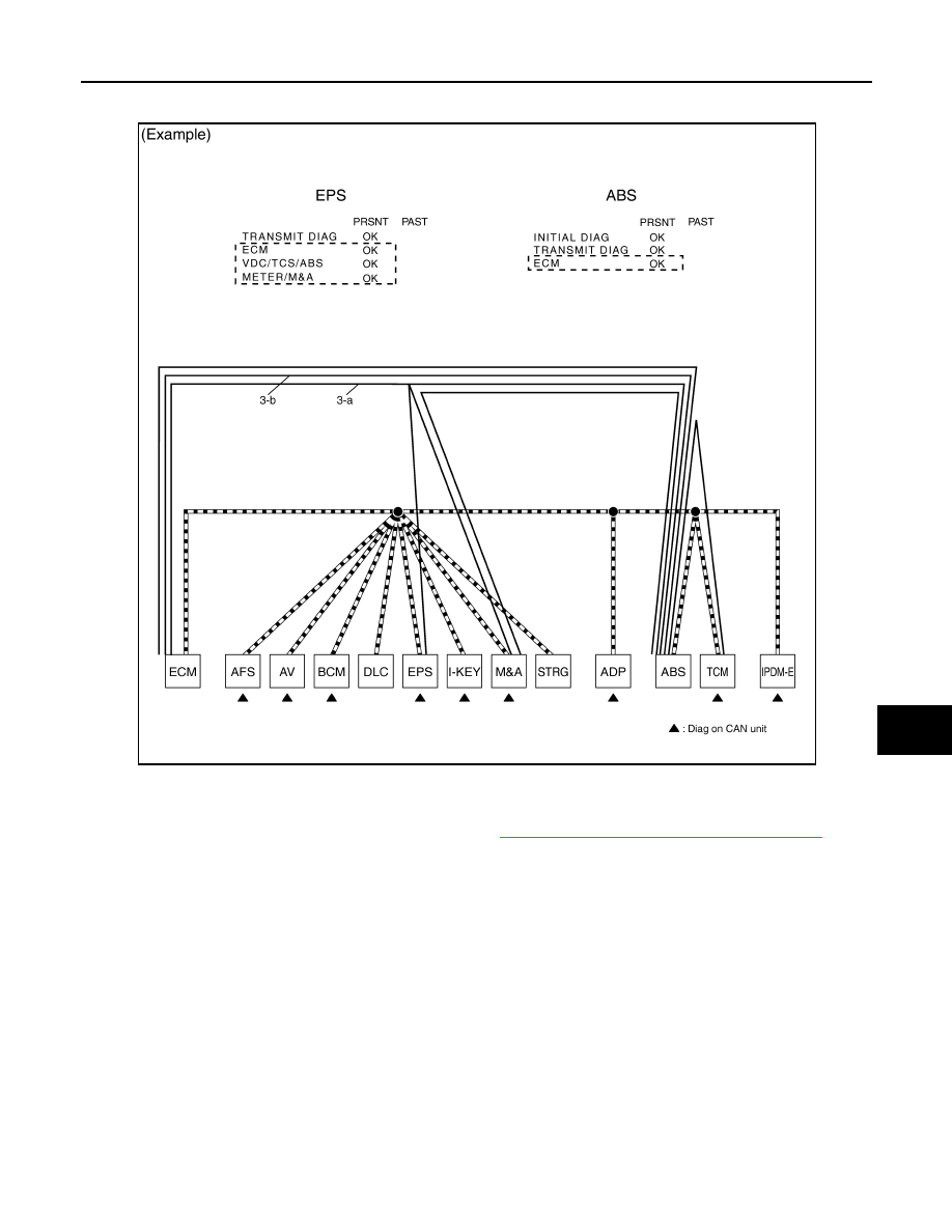
3.
CAN DIAG SUPPORT MNTR (without PAST): Check the CAN DIAG SUPPORT MNTR (without PAST) of
units indicating “U1000” or “U1001” on SELF-DIAG RESULTS. Draw a line on the diagnosis sheet to indi-
cate the possible error circuit.
NOTE:
• While an error occurred in the past according to SELF-DIAG RESULTS, it is unclear which signal is not
received. Assume that errors were detected from all reception items.
• Draw a single line among the unit and all reception items. (Work flow differs from CAN DIAG SUPPORT
MNTR (with PAST).)
a.
Reception item of “EPS”: Assume that the unit could not receive the signals from ECM, ABS, and M&A.
Draw a line among EPS, ECM, ABS, and M&A (line 3-a in the figure below).
PKID1222E
TROUBLE DIAGNOSES WORK FLOW
LAN-31
< SERVICE INFORMATION >
[CAN FUNDAMENTAL]
C
D
E
F
G
H
I
J
L
M
A
B
LAN
N
O
P
b.
Reception item of “ABS”: Assume that the unit could not receive the signal from ECM. Draw a line
between ABS and ECM (line 3-b in the figure below).
4.
Search for the possible cause using CAN communication signal chart using information from the interview
with the customer.
NOTE:
For the details of CAN communication signal, refer to
LAN-44, "CAN Communication Signal Chart"
a.
ABS warning lamp turned ON and speedometer did not move: This means that “ABS warning lamp signal”
and “Vehicle speed signal” could not communicate between M&A and ABS (4-a in the figure below).
PKID1223E

LAN-32
< SERVICE INFORMATION >
[CAN FUNDAMENTAL]
TROUBLE DIAGNOSES WORK FLOW
b.
The tachometer moved normally: This means that “Engine speed signal” could communicate normally
between ECM and M&A (4-b in the figure below).
5.
Fill out the diagnosis sheet based on information from step 4.
a.
The ABS warning lamp turned ON and speedometer did not move: Assume that a possible cause is no
communication between M&A and ABS. Draw a line between M&A and ABS. (Line 5-a in the figure
below).
SKIB8895E
Нет комментариевНе стесняйтесь поделиться с нами вашим ценным мнением.
Текст