Infiniti FX35 / FX45. Manual — part 761
TROUBLE DIAGNOSES WORK FLOW
LAN-21
< SERVICE INFORMATION >
[CAN FUNDAMENTAL]
C
D
E
F
G
H
I
J
L
M
A
B
LAN
N
O
P
• For abbreviations, refer to
.
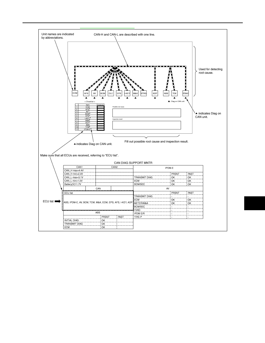
DETECT THE ROOT CAUSE
Identify the root cause using the created diagnosis sheet.
Identifying the root cause
• Draw a line on the diagnosis sheet to indicate the possible cause. Narrow the search.
NOTE:
• Color-code when drawing lines.
• Do not draw a line onto a existing line.
• Drawing a line is not necessary if the circuit is shorted. Refer to "Present Error — Short Circuit —", "Past
Error — Short Circuit —".
Refer to the following for details of the trouble diagnosis procedure.
• "Present Error — Open Circuit —"
• "Present Error — Short Circuit —"
• "Past Error — Open Circuit —"
• "Past Error — Short Circuit —"
NOTE:
When the root cause appears to be a branch line or short circuit, be sure to check the control unit as well as
the communication line.
Present Error — Open Circuit —
PKID1213E
LAN-22
< SERVICE INFORMATION >
[CAN FUNDAMENTAL]
TROUBLE DIAGNOSES WORK FLOW
Identify the error circuit using information from the “CAN DIAG SUPPORT MNTR” (“ECU list” included).
1.
ECU list: Check the items indicated in “ECU list”. Draw a line on the diagnosis sheet to indicate the error
circuit.
NOTE:
CAN communication line has no error if units other than Diag on CAN units are not indicated. An error
may be on the power supply of the control unit, DDL1 line or DDL2 line.
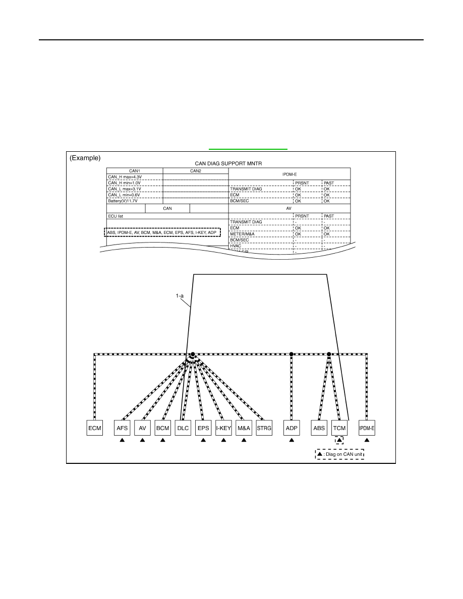
a.
“TCM” which is Diag on CAN unit, is not indicated on “ECU list”. This indicates that DLC is not receiving a
signal from TCM. Draw a line to indicate an error between DLC and TCM (line 1-a in the figure below).
NOTE:
• Diag on CAN units are not indicated on the “ECU list” when the CAN line between Diag on CAN unit and
the data link connector is open.
• For a description of Diag on CAN, refer to
2.
CAN DIAG SUPPORT MNTR: Check each item on “CAN DIAG SUPPORT MNTR”. Draw a line on the
diagnosis sheet to indicate the error circuit.
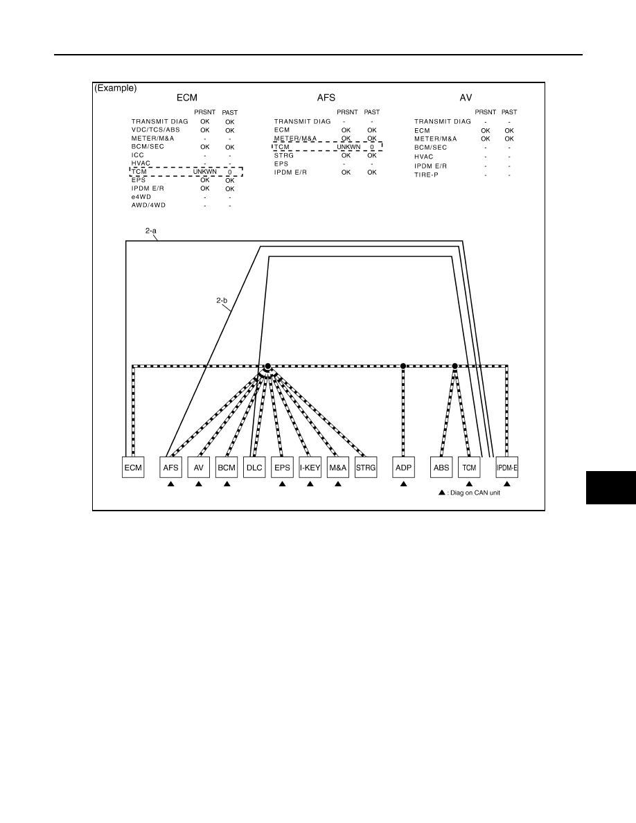
a.
Reception item of “ECM”: On “TCM”, “UNKWN” is indicated. This means ECM cannot receive the signal
from TCM. Draw a line to indicate an error between ECM and TCM (line 2-a in the figure below).
NOTE:
If “UNKWN” is indicated on “TRANSMIT DIAG”, then the control unit cannot transmit CAN communication
signal to each unit. Draw a line between the control unit and the splice.
b.
Reception item of “AFS”: On “TCM”, “UNKWN” is indicated. This means AFS cannot receive the signal
from TCM. Draw a line to indicate an error between AFS and TCM (line 2-b in the figure below).
PKID1214E
TROUBLE DIAGNOSES WORK FLOW
LAN-23
< SERVICE INFORMATION >
[CAN FUNDAMENTAL]
C
D
E
F
G
H
I
J
L
M
A
B
LAN
N
O
P
c.
Reception item of “AV”: “UNKWN” is not indicated. This indicates normal communication between AV and
its receiving units. Do not draw any line.
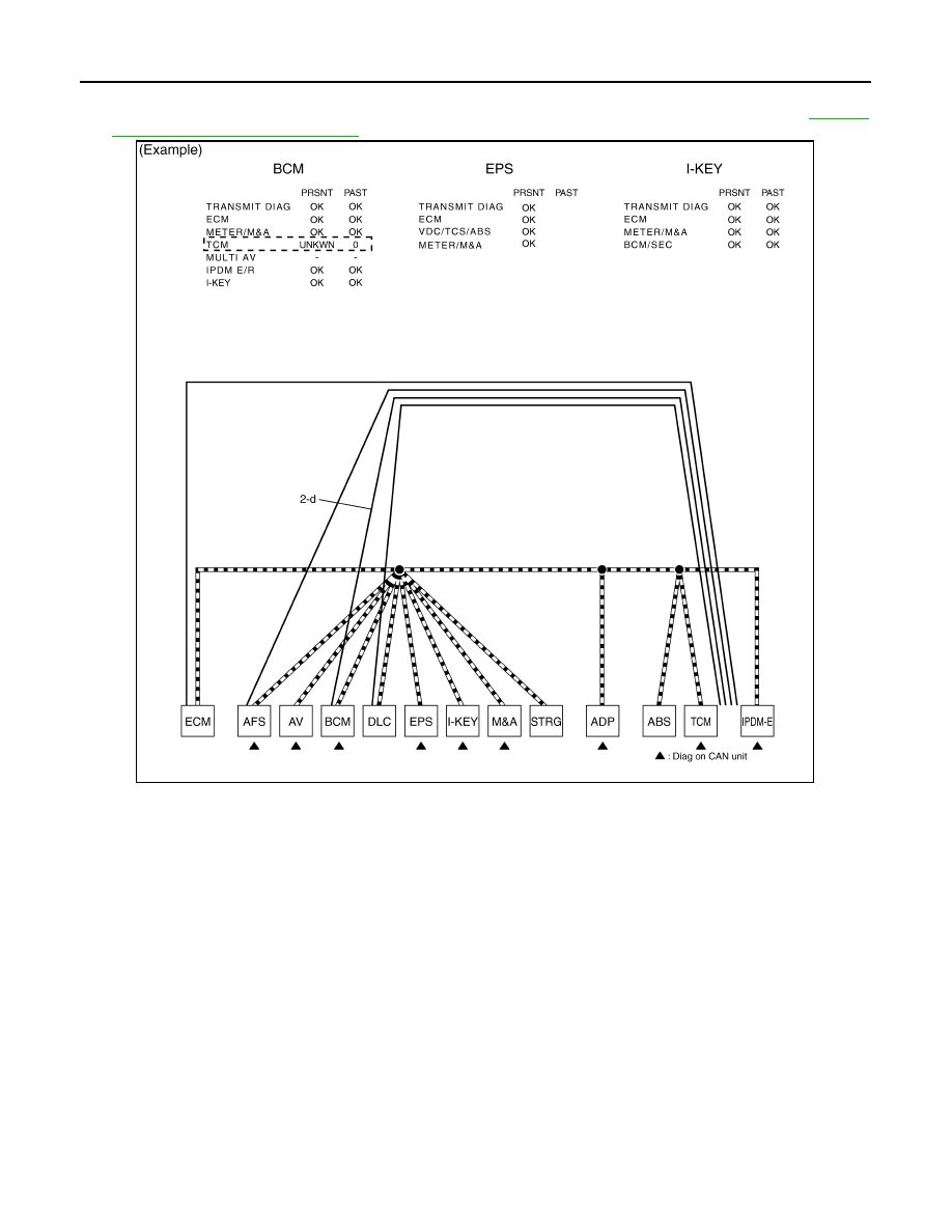
d.
Reception item of “BCM”: On “TCM”, “UNKWN” is indicated. This means BCM cannot receive the signal
from TCM. Draw a line to indicate an error between BCM and TCM (line 2-d in the figure below).
e.
Reception item of “EPS” and “I-KEY”: “UNKWN” is not indicated. This indicates normal communication
between EPS and I-KEY and their receiving units. Do not draw any line.
NOTE:
PKID1215E
LAN-24
< SERVICE INFORMATION >
[CAN FUNDAMENTAL]
TROUBLE DIAGNOSES WORK FLOW
On CAN DIAG SUPPORT MNTR (without PAST), “UNKWN” is indicated even though the item is not used
in the trouble diagnosis. For the details of each item on CAN diagnostic support monitor, refer to
"CAN Diagnostic Support Monitor"
.
f.
Reception item of “M&A”: On “TCM”, “UNKWN” is indicated. This means M&A cannot receive the signal
from TCM. Draw a line to indicate an error between M&A and TCM (line 2-f in the figure below).
g.
Reception item of “ADP”: On “TCM”, “UNKWN” is indicated. This means ADP cannot receive the signal
from TCM. Draw a line to indicate an error between ADP and TCM (line 2-g in the figure below).
PKID1216E
Нет комментариевНе стесняйтесь поделиться с нами вашим ценным мнением.
Текст