Infiniti FX35 / FX45. Manual — part 721
HOW TO USE THIS MANUAL
GI-19
< SERVICE INFORMATION >
C
D
E
F
G
H
I
J
K
L
M
B
GI
N
O
P
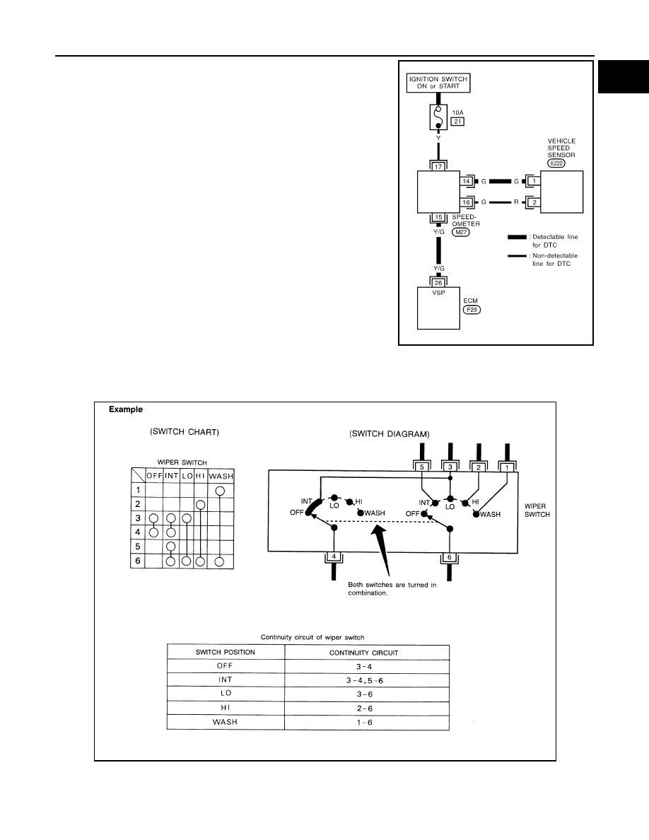
• A line with regular weight (wider line) represents a “detectable line
for DTC (Diagnostic Trouble Code)”. A “detectable line for DTC” is
a circuit in which ECM can detect its malfunctions with the on
board diagnostic system.
• A line with less weight (thinner line) represents a “non-detectable
line for DTC”. A “non-detectable line for DTC” is a circuit in which
ECM cannot detect its malfunctions with the on board diagnostic
system.
Multiple Switch
The continuity of multiple switch is described in two ways as shown below.
• The switch chart is used in schematic diagrams.
• The switch diagram is used in wiring diagrams.
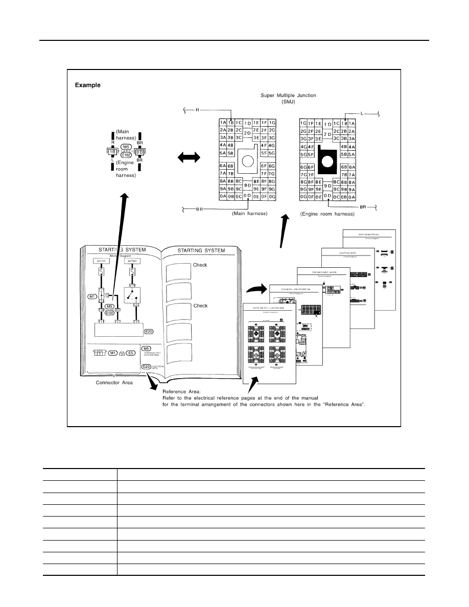
Reference Area
SGI862-B
SGI875
GI-20
< SERVICE INFORMATION >
HOW TO USE THIS MANUAL
The Reference Area of the wiring diagram contains references to additional electrical reference pages at the
end of the manual. If connector numbers and titles are shown in the Reference Area of the wiring diagram,
these connector symbols are not shown in the Connector Area.
Abbreviations
INFOID:0000000001325670
The following ABBREVIATIONS are used:
SGI092A
ABBREVIATION
DESCRIPTION
A/C
Air Conditioner
A/T
Automatic Transaxle/Transmission
ATF
Automatic Transmission Fluid
D
1
Drive range 1st gear
D
2
Drive range 2nd gear
D
3
Drive range 3rd gear
D
4
Drive range 4th gear
FR, RR
Front, Rear
HOW TO USE THIS MANUAL
GI-21
< SERVICE INFORMATION >
C
D
E
F
G
H
I
J
K
L
M
B
GI
N
O
P
LH, RH
Left-Hand, Right-Hand
M/T
Manual Transaxle/Transmission
OD
Overdrive
P/S
Power Steering
SAE
Society of Automotive Engineers, Inc.
SDS
Service Data and Specifications
SST
Special Service Tools
2WD
2-Wheel Drive
2
2
2nd range 2nd gear
2
1
2nd range 1st gear
1
2
1st range 2nd gear
1
1
1st range 1st gear
ABBREVIATION
DESCRIPTION
GI-22
< SERVICE INFORMATION >
SERVICE INFORMATION FOR ELECTRICAL INCIDENT
SERVICE INFORMATION FOR ELECTRICAL INCIDENT
How to Check Terminal
INFOID:0000000001325671
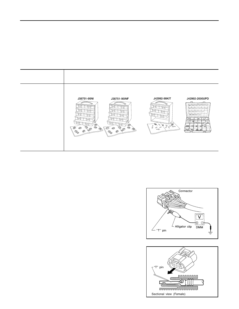
CONNECTOR AND TERMINAL PIN KIT
Use the connector and terminal pin kits listed below when replacing connectors or terminals.
The connector and terminal pin kits contain some of the most commonly used NISSAN/INFINITI connectors
and terminals. For detailed connector and terminal pin replacement procedures, refer to the latest NISSAN/
INFINITI CONNECTOR AND TERMINAL PIN SERVICE MANUAL.
HOW TO PROBE CONNECTORS
Connector damage and an intermittent connection can result from improperly probing of the connector during
circuit checks.
The probe of a digital multimeter (DMM) may not correctly fit the connector cavity. To correctly probe the con-
nector, follow the procedures below using a “T” pin. For the best contact grasp the “T” pin using an alligator
clip.
Probing from Harness Side
Standard type (not waterproof type) connector should be probed
from harness side with “T” pin.
• If the connector has a rear cover such as a ECM connector,
remove the rear cover before probing the terminal.
• Do not probe waterproof connector from harness side. Damage to
the seal between wire and connector may result.
Probing from Terminal Side
FEMALE TERMINAL
• There is a small notch above each female terminal. Probe each
terminal with the “T” pin through the notch.
Do not insert any object other than the same type male terminal
into female terminal.
Tool number
(Kent-Moore No.)
Tool name
Description
-
(J38751-95NI)
Connector and terminal
pin kit (NISSAN)
-
(J38751-95INF)
Connector and terminal
pin kit (INFINITI)
-
(J42992-98KIT)
OBD and terminal repair
kit
-
(J42992-2000UPD)
OBD-II Connector Kit Up-
date
WAIA0004E
WAIA0005E
SGI841
SEL265V
Нет комментариевНе стесняйтесь поделиться с нами вашим ценным мнением.
Текст