Infiniti FX35 / FX45. Manual — part 720
HOW TO USE THIS MANUAL
GI-15
< SERVICE INFORMATION >
C
D
E
F
G
H
I
J
K
L
M
B
GI
N
O
P
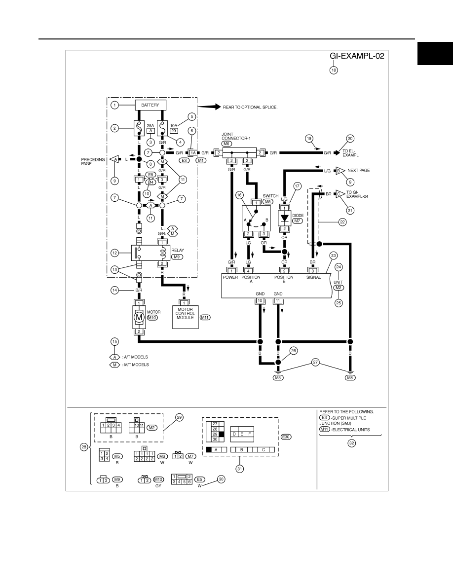
• For detail, refer to following “DESCRIPTION”.
SGI091A
GI-16
< SERVICE INFORMATION >
HOW TO USE THIS MANUAL
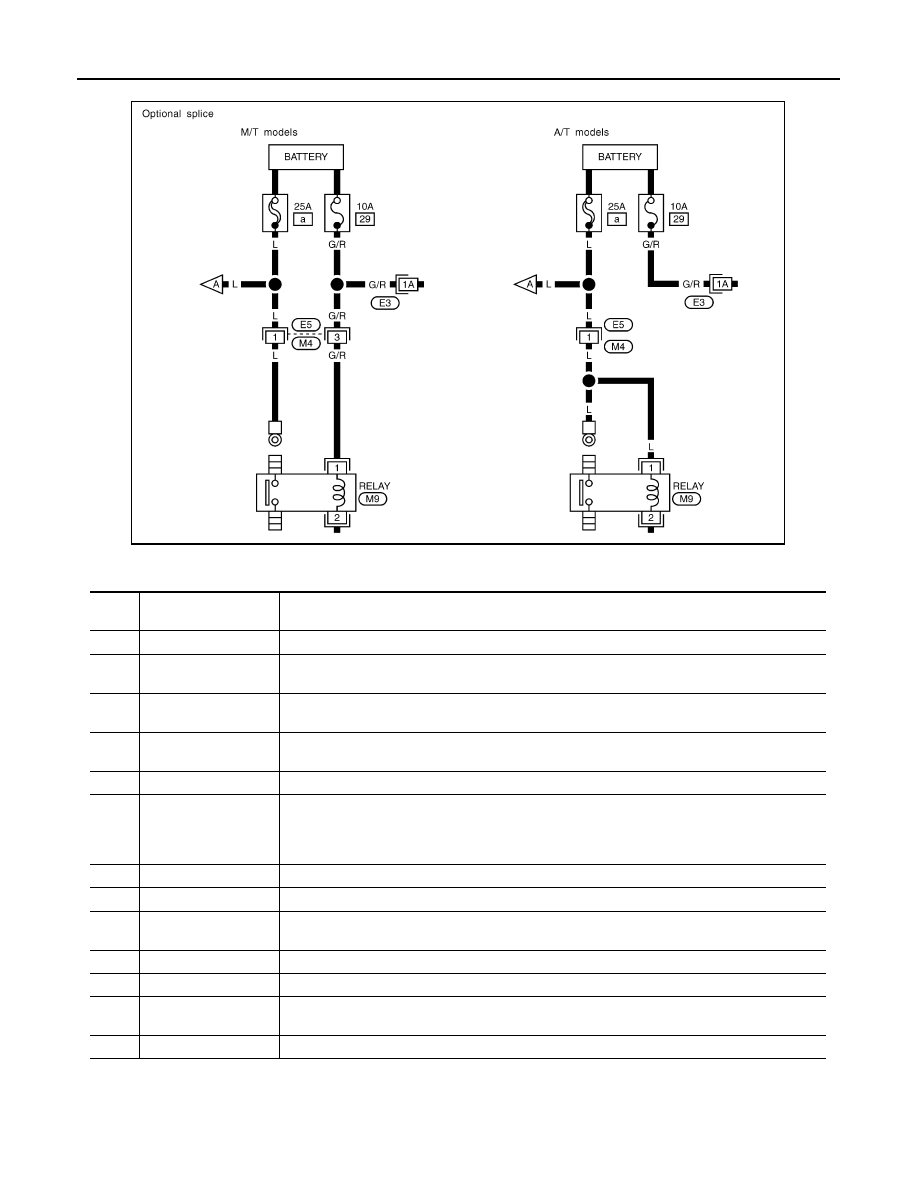
Optional Splice
DESCRIPTION
SGI942
Num-
ber
Item
Description
1
Power condition
• This shows the condition when the system receives battery positive voltage (can be operated).
2
Fusible link
• The double line shows that this is a fusible link.
• The open circle shows current flow in, and the shaded circle shows current flow out.
3
Fusible link/fuse loca-
tion
• This shows the location of the fusible link or fuse in the fusible link or fuse box. For arrange-
ment, refer to PG section, POWER SUPPLY ROUTING.
4
Fuse
• The single line shows that this is a fuse.
• The open circle shows current flow in, and the shaded circle shows current flow out.
5
Current rating
• This shows the current rating of the fusible link or fuse.
6
Connectors
• This shows that connector E3 is female and connector M1 is male.
• The G/R wire is located in the 1A terminal of both connectors.
• Terminal number with an alphabet (1A, 5B, etc.) indicates that the connector is SMJ connector.
Refer to PG section, SMJ (SUPER MULTIPLE JUNCTION).
7
Optional splice
• The open circle shows that the splice is optional depending on vehicle application.
8
Splice
• The shaded circle shows that the splice is always on the vehicle.
9
Page crossing
• This arrow shows that the circuit continues to an adjacent page.
• The A will match with the A on the preceding or next page.
10
Common connector
• The dotted lines between terminals show that these terminals are part of the same connector.
11
Option abbreviation
• This shows that the circuit is optional depending on vehicle application.
12
Relay
• This shows an internal representation of the relay. For details, refer to PG section, STAN-
DARDIZED RELAY.
13
Connectors
• This shows that the connector is connected to the body or a terminal with bolt or nut.

HOW TO USE THIS MANUAL
GI-17
< SERVICE INFORMATION >
C
D
E
F
G
H
I
J
K
L
M
B
GI
N
O
P
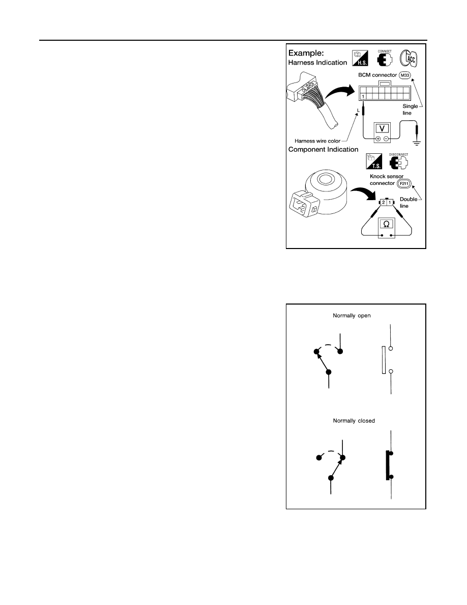
Harness Indication
14
Wire color
• This shows a code for the color of the wire.
B = Black
W = White
R = Red
G = Green
L = Blue
Y = Yellow
LG = Light Green
BR = Brown
OR or O = Orange
P = Pink
PU or V (Violet) = Purple
GY or GR = Gray
SB = Sky Blue
CH = Dark Brown
DG = Dark Green
When the wire color is striped, the base color is given first, followed by the stripe color as shown
below:
Example: L/W = Blue with White Stripe
15
Option description
• This shows a description of the option abbreviation used on the page.
16
Switch
• This shows that continuity exists between terminals 1 and 2 when the switch is in the A posi-
tion. Continuity exists between terminals 1 and 3 when the switch is in the B position.
17
Assembly parts
• Connector terminal in component shows that it is a harness incorporated assembly.
18
Cell code
• This identifies each page of the wiring diagram by section, system and wiring diagram page
number.
19
Current flow arrow
• Arrow indicates electric current flow, especially where the direction of standard flow (vertically
downward or horizontally from left to right) is difficult to follow.
• A double arrow “
” shows that current can flow in either direction depending on circuit
operation.
20
System branch
• This shows that the system branches to another system identified by cell code (section and
system).
21
Page crossing
• This arrow shows that the circuit continues to another page identified by cell code.
• The C will match with the C on another page within the system other than the next or preceding
pages.
22
Shielded line
• The line enclosed by broken line circle shows shield wire.
23
Component box in
wave line
• This shows that another part of the component is also shown on another page (indicated by
wave line) within the system.
24
Component name
• This shows the name of a component.
25
Connector number
• This shows the connector number.
• The letter shows which harness the connector is located in.
• Example: M: main harness. For detail and to locate the connector, refer to PG section "Main
Harness", “Harness Layout”. A coordinate grid is included for complex harnesses to aid in lo-
cating connectors.
26
Ground (GND)
• The line spliced and grounded under wire color shows that ground line is spliced at the ground-
ed connector.
27
Ground (GND)
• This shows the ground connection. For detailed ground distribution information, refer to
"Ground Distribution" in PG section.
28
Connector views
• This area shows the connector faces of the components in the wiring diagram on the page.
29
Common component
• Connectors enclosed in broken line show that these connectors belong to the same compo-
nent.
30
Connector color
• This shows a code for the color of the connector. For code meaning, refer to wire color codes,
Number 14 of this chart.
31
Fusible link and fuse
box
• This shows the arrangement of fusible link(s) and fuse(s), used for connector views of "POW-
ER SUPPLY ROUTING" in PG section.
The open square shows current flow in, and the shaded square shows current flow out.
32
Reference area
• This shows that more information on the Super Multiple Junction (SMJ) and Joint Connectors
(J/C) exists on the PG section. Refer to "Reference Area" for details.
Num-
ber
Item
Description
GI-18
< SERVICE INFORMATION >
HOW TO USE THIS MANUAL
• Letter designations next to test meter probe indicate harness (con-
nector) wire color.
• Connector numbers in a single circle M33 indicate harness con-
nectors.
Component Indication
Connector numbers in a double circle F211 indicate component connectors.
Switch Positions
Switches are shown in wiring diagrams as if the vehicle is in the “normal” condition.
A vehicle is in the “normal” condition when:
• ignition switch is “OFF”,
• doors, hood and trunk lid/back door are closed,
• pedals are not depressed, and
• parking brake is released.
Detectable Lines and Non-Detectable Lines
In some wiring diagrams, two kinds of lines, representing wires, with different weight are used.
AGI070
SGI860
Нет комментариевНе стесняйтесь поделиться с нами вашим ценным мнением.
Текст