Infiniti FX35 / FX45. Manual — part 968

TROUBLE DIAGNOSIS FOR SELF-DIAGNOSTIC ITEMS
WT-29
< SERVICE INFORMATION >
C
D
F
G
H
I
J
K
L
M
A
B
WT
N
O
P
YES
>> GO TO 3.
NO
>> Go to the inspection 1. Refer to
WT-28, "Transmitter or Control Unit (BCM)"
.
3.
VEHICLE DRIVING
• Drive at a speed of 40 km/h (25 MPH) or more for 3 minutes, and then drive the vehicle at any speed for 10
minutes. Then check all tire pressures with CONSULT-III “DATA MONITOR ITEM” within 5 minutes.
Does “DATA MONITOR ITEM” displayed tire pressure as normal without any warning lamp?
YES
>> INSPECTION END.
NO
>> Replace malfunctioning transmitter, and perform “Step 3” again.
Transmitter - 2
INFOID:0000000001327591
MALFUNCTION CODE NO. 35, 36, 37 OR 38
1.
CHECK ALL TIRE PRESSURES
• Check all tire pressures. Refer to
Are there any tires whose pressure is “64 psi” or more?
YES
>> Adjust tire pressure to specified value.
NO
>> GO TO 2.
2.
VEHICLE DRIVING
1.
Perform ID registration of all transmitters.
2.
Drive at a speed of 40 km/h (25 MPH) or more for several minutes without stopping.
Check all tire pressures with CONSULT-III “DATA MONITOR ITEM” within 15 minutes after vehicle speed
become 17 km/h (11 MPH).
>> Replace transmitter with new one if “DATA MONITOR ITEM” displayed 64 psi or more. Then GO
TO 3.
3.
ID REGISTRATION AND VEHICLE DRIVING
1.
Perform ID registration of all transmitters.
2.
Drive at a speed of 40 km/h (25 MPH) or more for 3 minutes, and then drive the vehicle at any speed for
10 minutes. Then check all tire pressures with CONSULT-III “DATA MONITOR ITEM” within 5 minutes.
Does “DATA MONITOR ITEM” display tire pressure as normal without any warning lamp?
YES
>> INSPECTION END
NO
>> Go to the inspection applicable to DTC.
Vehicle Speed Signal
INFOID:0000000001327592
MALFUNCTION CODE NO. 52
1.
CHECK SELF-DIAGNOSIS RESULTS
1.
Select “SELF-DIAG RESULTS” on “SELECT DIAG MODE” screen.
2.
Check display contents in self-diagnostic results.
Is “CAN COMM CIRCUIT” displayed in the self-diagnosis display items?
YES
>> Malfunction in CAN communication system. Go to
LAN-43, "CAN System Specification Chart"
NO
>> No malfunction. Check combination meter refer to
WT-30
< SERVICE INFORMATION >
TROUBLE DIAGNOSIS FOR SYMPTOMS
TROUBLE DIAGNOSIS FOR SYMPTOMS
Low Tire Pressure Warning Lamp Does Not Come On When Ignition Switch Is Turned
On
INFOID:0000000001327593
DIAGNOSTIC PROCEDURE
1.
CHECK SELF-DIAGNOSIS RESULTS
1.
Select “SELF-DIAG RESULTS” on “SELECT DIAG MODE” screen.
2.
Check display contents in self-diagnostic results.
Is “CAN COMM CIRCUIT” displayed in the self-diagnosis display items?
YES
>> Malfunction in CAN communication system. Go to
LAN-43, "CAN System Specification Chart"
NO
>> No malfunction. GO TO 2.
2.
CHECK COMBINATION METER
• Check combination meter function.
OK or NG
OK
>> GO TO 3.
NG
>> Check combination meter. Refer to
.
3.
CHECK LOW TIRE PRESSURE WARNING LAMP
• Disconnect BCM harness connectors M3 and M4.
Does the warning lamp activate?
YES
>> Replace BCM. Refer to
BCS-13, "Removal and Installation of BCM"
.
NO
>> Check combination meter and repair or replace.
Low Tire Pressure Warning Lamp Stays On When Ignition Switch Is Turned On
INFOID:0000000001327594
DIAGNOSTIC PROCEDURE
1.
CHECK CONNECTOR
1.
Disconnect BCM harness connectors M3 and M4.
2.
Check terminals for damage or loose connections.
OK or NG
OK
>> GO TO 2.
NG
>> Repair or replace damaged parts.
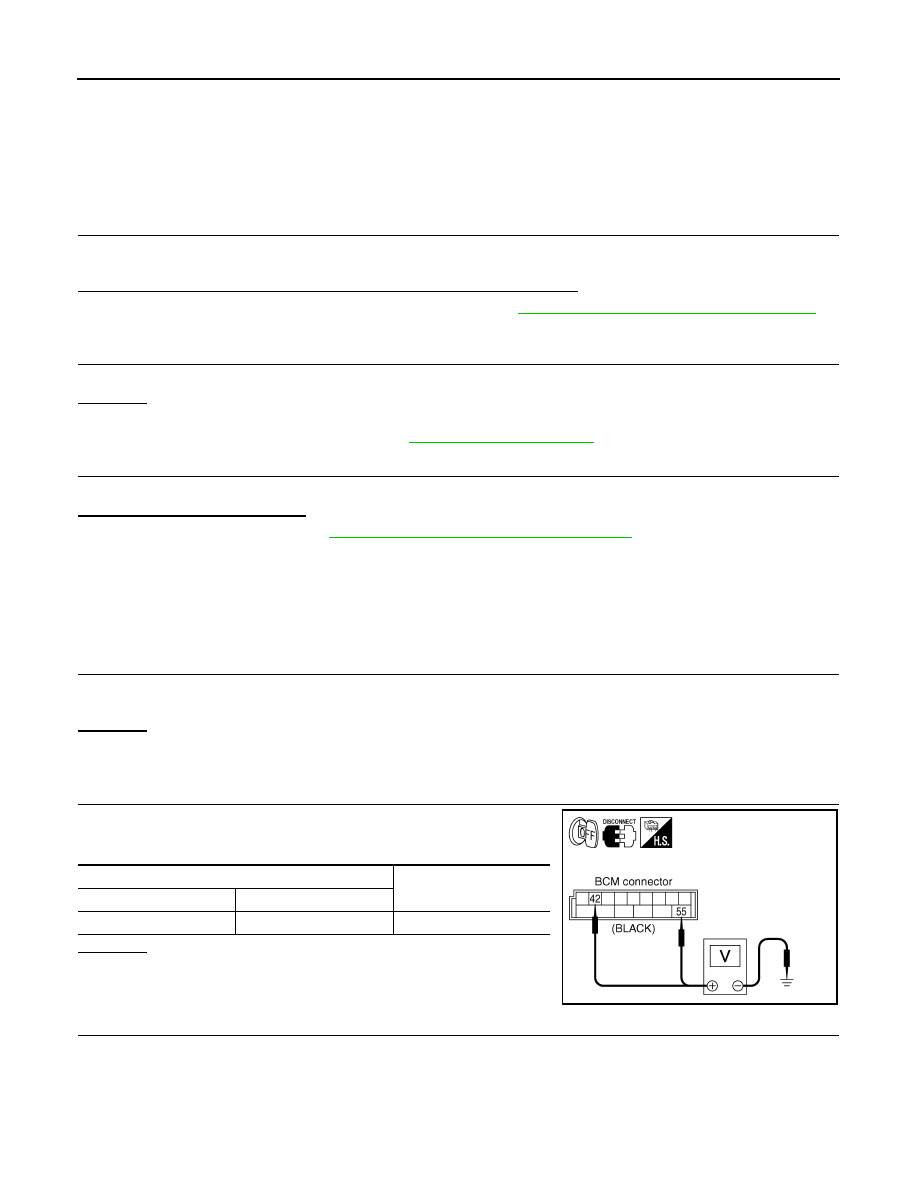
2.
CHECK POWER SUPPLY CIRCUIT (BATTERY)
Make sure voltage between BCM harness connector M4 and
ground.
OK or NG
OK
>> GO TO 3.
NG
>> Check BCM power supply circuit for open or short.
3.
CHECK POWER SUPPLY CIRCUIT (IGN)
1.
Turn ignition switch ON.
Terminal
Voltage
(+)
(–)
42, 55
Ground
12V
SEIA0435E
TROUBLE DIAGNOSIS FOR SYMPTOMS
WT-31
< SERVICE INFORMATION >
C
D
F
G
H
I
J
K
L
M
A
B
WT
N
O
P
2.
Make sure voltage between BCM harness connector M3 and
ground.
OK or NG
OK
>> GO TO 4.
NG
>> Check BCM power supply circuit for open or short.
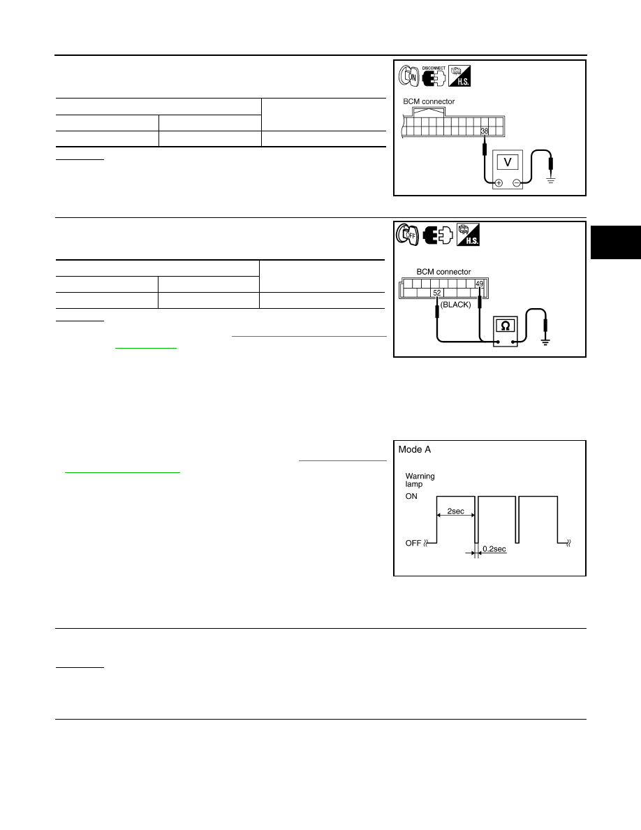
4.
CHECK GROUND CIRCUIT
• Check continuity between BCM harness connector M4 and
ground.
OK or NG
OK
>> Replace BCM. Refer to
BCS-13, "Removal and Installa-
NG
>> Repair or replace BCM ground circuit.
Low Tire Pressure Warning Lamp Blinks When Ignition Switch Is Turned On
INFOID:0000000001327595
NOTE:
If warning lamp blink below, the system is normal.
Blink Mode A
• This mode shows transmitter status is OFF-mode.
Perform transmitter wake up operation. Refer to
.
DIAGNOSTIC PROCEDURE
1.
CHECK CONNECTOR
1.
Disconnect BCM harness connector M3.
2.
Check terminals for damage or loose connections.
OK or NG
OK
>> GO TO 2.
NG
>> Repair or replace damaged parts.
2.
CHECK TIRE PRESSURE WARNING CHECK SWITCH CIRCUIT
Terminal
Voltage
(+)
(–)
38
Ground
12V
SEIA0436E
Terminal
Continuity
(+)
(–)
49, 52
Ground
Yes
SEIA0610E
SEIA0347E

WT-32
< SERVICE INFORMATION >
TROUBLE DIAGNOSIS FOR SYMPTOMS
• Check continuity between BCM harness connector M3 and
ground.
OK or NG
OK
BCS-13, "Removal and Installa-
NG
>> Repair or replace harness connector.
Run-Flat Tire Warning Lamp Stays On When Ignition Switch Is Turned On
INFOID:0000000001327596
DIAGNOSTIC PROCEDURE
1.
CHECK ALL TIRE PRESSURES
• Check all tire pressures. Refer to
OK or NG
OK
>> Check combination meter. Refer to
.
NG
>> Adjust tire pressure to specified value or change the tires.
Turn Signal Lamp Blinks When Ignition Switch Is Turned On
INFOID:0000000001327597
DIAGNOSTIC PROCEDURE
1.
CHECK TIRE PRESSURE WARNING CHECK SWITCH CIRCUIT
• Check continuity between BCM harness connector M3 and
ground.
OK or NG
OK
>> Check turn signal lamp operation. Refer to
NG
>> Repair or replace harness connector.
ID Registration Cannot Be Completed
INFOID:0000000001327598
DIAGNOSTIC PROCEDURE
1.
ID REGISTRATION (ALL)
• Perform ID registration of all transmitters.
Can ID registration of all transmitters be completed?
YES
>> INSPECTION END
NO
>> Go to
.
Terminal
Continuity
(+)
(–)
15
Ground
No
SEIA0438E
Terminal
Continuity
(+)
(–)
15
Ground
No
SEIA0438E
Нет комментариевНе стесняйтесь поделиться с нами вашим ценным мнением.
Текст