Infiniti FX35 / FX45. Manual — part 969

REMOVAL AND INSTALLATION
WT-33
< SERVICE INFORMATION >
C
D
F
G
H
I
J
K
L
M
A
B
WT
N
O
P
REMOVAL AND INSTALLATION
Transmitter
INFOID:0000000001327599
REMOVAL
1.
Deflate tire. Unscrew transmitter retaining nut and allow transmitter to fall into tire.
2.
Gently bounce tire so that transmitter falls to bottom of tire.
Place on tire changing machine and break both tire beads
ensuring that the transmitter remains at the bottom of the tire.
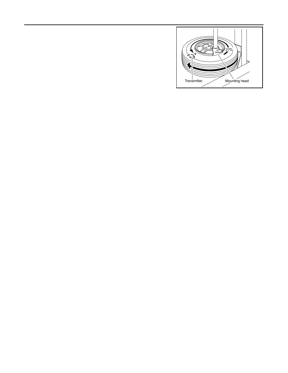
3.
Turn tire so that valve hole is at bottom and bounce so that
transmitter is near valve hole. Carefully lift tire onto turntable and
position valve hole (and transmitter) 270 degree from mounting/
dismounting head.
4.
Lubricate tire well and remove first side of the tire. Reach inside
the tire and remove the transmitter.
INSTALLATION
1.
Put first side of tire onto rim.
2.
Mount transmitter on rim and tighten nut.
SEIA0047E
SEIA0048E
SEIA0049E
SEIA0521E
WT-34
< SERVICE INFORMATION >
REMOVAL AND INSTALLATION
3.
Place wheel on turntable of tire machine. Ensure that transmitter
is 270 degree from mounting head when second side of tire is
fitted.
NOTE:
Do not touch transmitter at mounting head.
4.
Lubricate tire well and fit second side of tire as normal. Ensure
that tire does not rotate relative to rim.
5.
Inflate tire and fit to appropriate wheel position.
SEIA0048E

SERVICE DATA AND SPECIFICATIONS (SDS)
WT-35
< SERVICE INFORMATION >
C
D
F
G
H
I
J
K
L
M
A
B
WT
N
O
P
SERVICE DATA AND SPECIFICATIONS (SDS)
Road Wheel
INFOID:0000000001327600
Tire
INFOID:0000000001327601
Unit: kPa (kg/cm
2
, psi)
Kind of wheel
Aluminum
Steel (for emergency use)
Maximum radial runout limit
Lateral deflection
Less than 0.3 mm (0.012 in)
Less than 1.5 mm (0.059 in)
Vertical deflection
Less than 0.3 mm (0.012 in)
Less than 1.5 mm (0.059 in)
Maximum allowable unbalance
Dynamic (At rim flange)
Less than 5.0 g (0.2 oz) (one side)
—
Static (At rim flange)
Less than 20 g (0.7 oz)
—
Tire size
Air pressure
Front
Rear
P265/60R18 109V
220 (2.2, 32)
220 (2.2, 32)
P265/50R20 106V
220 (2.2, 32)
220 (2.2, 32)
T175/90D18 110M
420 (4.2, 60)
420 (4.2, 60)
WW-1
ELECTRICAL
C
D
E
F
G
H
I
J
L
M
SECTION
WW
A
B
WW
N
O
P
CONTENTS
WIPER, WASHER & HORN
SERVICE INFORMATION . . . . . . .
PRECAUTION . . . . . . . . . . . . . .
Precaution for Procedure without Cowl Top Cover
. ..
FRONT WIPER AND WASHER SYSTEM . . ..
Component Parts and Harness Connector Loca-
tion . . . . . . . . . . . . . . . . . . ....
System Description . . . . . . . . . . . . ...
CAN Communication System Description . . . .....
CAN Communication Unit . . . . . . . . . .....
Schematic . . . . . . . . . . . . . . . .....
Wiring Diagram - WIPER - . . . . . . . . . ....
Terminal and Reference Value for BCM . . . . .
Terminal and Reference Value for IPDM E/R . . .
How to Proceed with Trouble Diagnosis . . . . .
Preliminary Check . . . . . . . . . . . . ...
CONSULT-III Functions (BCM) . . . . . . . ...
CONSULT-III Functions (IPDM E/R) . . . . . ...
Front Wiper Does Not Operate . . . . . . . ...
Front Wiper Does Not Return to Stop Position . ...
Only Front Wiper Low Does Not Operate . . . ...
Only Front Wiper High Does Not Operate . . . ...
Only Front Wiper Intermittent Does Not Operate .
Front Wiper Interval Time Is Not Controlled by Ve-
hicle Speed . . . . . . . . . . . . . . . .
Front Wiper Intermittent Operation Switch Posi-
tion Cannot Be Adjusted . . . . . . . . . . .
Wiper Does Not Wipe When Front Washer Oper-
ates . . . . . . . . . . . . . . . . . . .
Front Wiper Does Not Stop . . . . . . . . . .
Removal and Installation of Front Wiper Arms, Ad-
justment of Wiper Arms Stop Location . . . . .
Removal and Installation of Front Wiper Drive As-
sembly . . . . . . . . . . . . . . . . . .
Disassembly and Assembly of Front Wiper Drive
Assembly . . . . . . . . . . . . . . . . .
Washer Nozzle Adjustment . . . . . . . . . .
Washer Tube Layout . . . . . . . . . . . ...
Removal and Installation of Front Washer Nozzle .
Removal and Installation of Front Washer Tube
Joint . . . . . . . . . . . . . . . . . . .
Inspection of Washer Nozzle . . . . . . . . ...
Inspection of Front Wiper and Washer Switch Cir-
cuit . . . . . . . . . . . . . . . . . . ...
Removal and Installation of Front Wiper and
Washer Switch . . . . . . . . . . . . . . .
Removal and Installation of Washer Tank . . . ...
Removal and Installation of Front and Rear Wash-
er Pump . . . . . . . . . . . . . . . . ...
REAR WIPER AND WASHER SYSTEM . . ..
Component Parts and Harness Connector Loca-
tion . . . . . . . . . . . . . . . . . . ...
System Description . . . . . . . . . . . . ..
Wiring Diagram - WIP/ R - . . . . . . . . . ...
Terminal and Reference Value for BCM . . . . ..
How to Proceed with Trouble Diagnosis . . . . ..
Preliminary Check . . . . . . . . . . . . ...
CONSULT-III Functions (BCM) . . . . . . . ...
Rear Wiper Does Not Operate . . . . . . . .
Rear Wiper Does Not Return to Stop Position . .
Only Rear Wiper ON Does Not Operate . . . . ..
Only Rear Wiper INT Does Not Operate . . . . .
Wiper Does Not Wipe When Rear Washer Oper-
ates . . . . . . . . . . . . . . . . . . ..
Rear Wipers Do Not Stop . . . . . . . . . .
Removal and Installation of Rear Wiper Arm, Ad-
justment of Wiper Arms Stop Location . . . . .
Removal and Installation of Rear Wiper Blade . .
Removal and Installation of Rear Wiper Motor . .
Washer Nozzle Adjustment . . . . . . . . . .
Washer Tube Layout . . . . . . . . . . . ...
Removal and Installation of Washer Nozzle . . .
Нет комментариевНе стесняйтесь поделиться с нами вашим ценным мнением.
Текст