Infiniti FX35 / FX45. Manual — part 534
DTC P0300 - P0308 MULTIPLE CYLINDER MISFIRE, NO. 1 - 8 CYLINDER MIS-
FIRE
EC-897
< SERVICE INFORMATION >
[VK45DE]
C
D
E
F
G
H
I
J
K
L
M
A
EC
N
P
O
4.
CHECK FUNCTION OF FUEL INJECTOR-I
Without CONSULT-III
1.
Turn ignition switch OFF.
2.
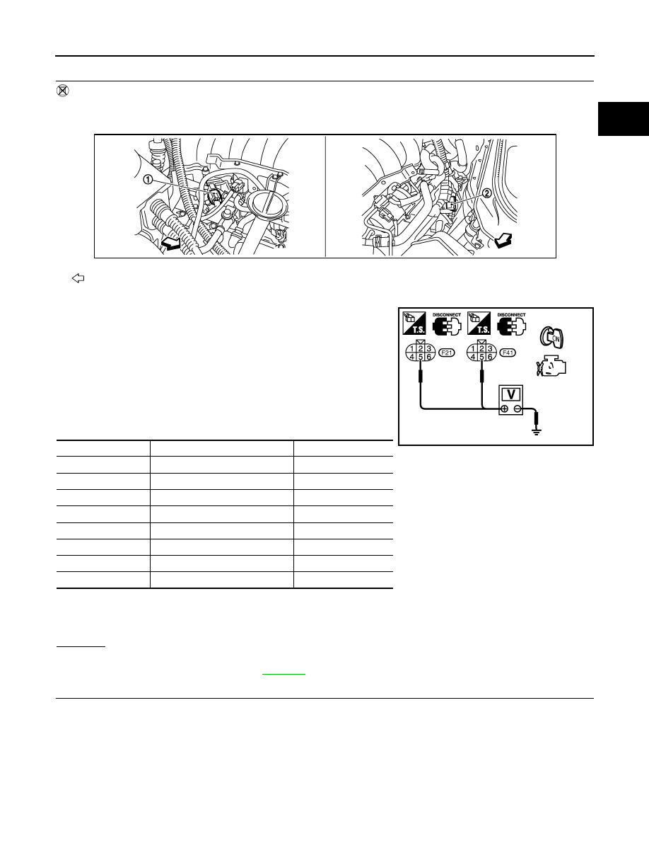
Disconnect harness connectors F21, F201 (Bank 1) and F41, F221 (Bank 2).
3.
Turn ignition switch ON.
4.
Check voltage between the following;
harness connector F21 terminal 5 and ground,
harness connector F41 terminal 5 and ground.
5.
Turn ignition switch OFF.
6.
Disconnect ECM harness connector.
7.
Check harness continuity between the following terminals.
8.
Also check harness for short to ground and short to power.
OK or NG
OK
>> GO TO 5.
NG
>> Perform trouble diagnosis for
5.
CHECK FUNCTION OF FUEL INJECTOR-II
: Vehicle front
1.
Harness connectors F41, F221
2.
Harness connectors F21, F201
Voltage: Battery voltage
Cylinder
Harness connector terminal
ECM terminal
1
F21 terminal 3
23
3
F21 terminal 2
22
5
F21 terminal 1
21
7
F21 terminal 6
44
2
F41 terminal 3
42
4
F41 terminal 2
41
6
F41 terminal 1
40
8
F41 terminal 6
63
Continuity should exist.
PBIB3248E
PBIB0180E
EC-898
< SERVICE INFORMATION >
[VK45DE]
DTC P0300 - P0308 MULTIPLE CYLINDER MISFIRE, NO. 1 - 8 CYLINDER MIS-
FIRE
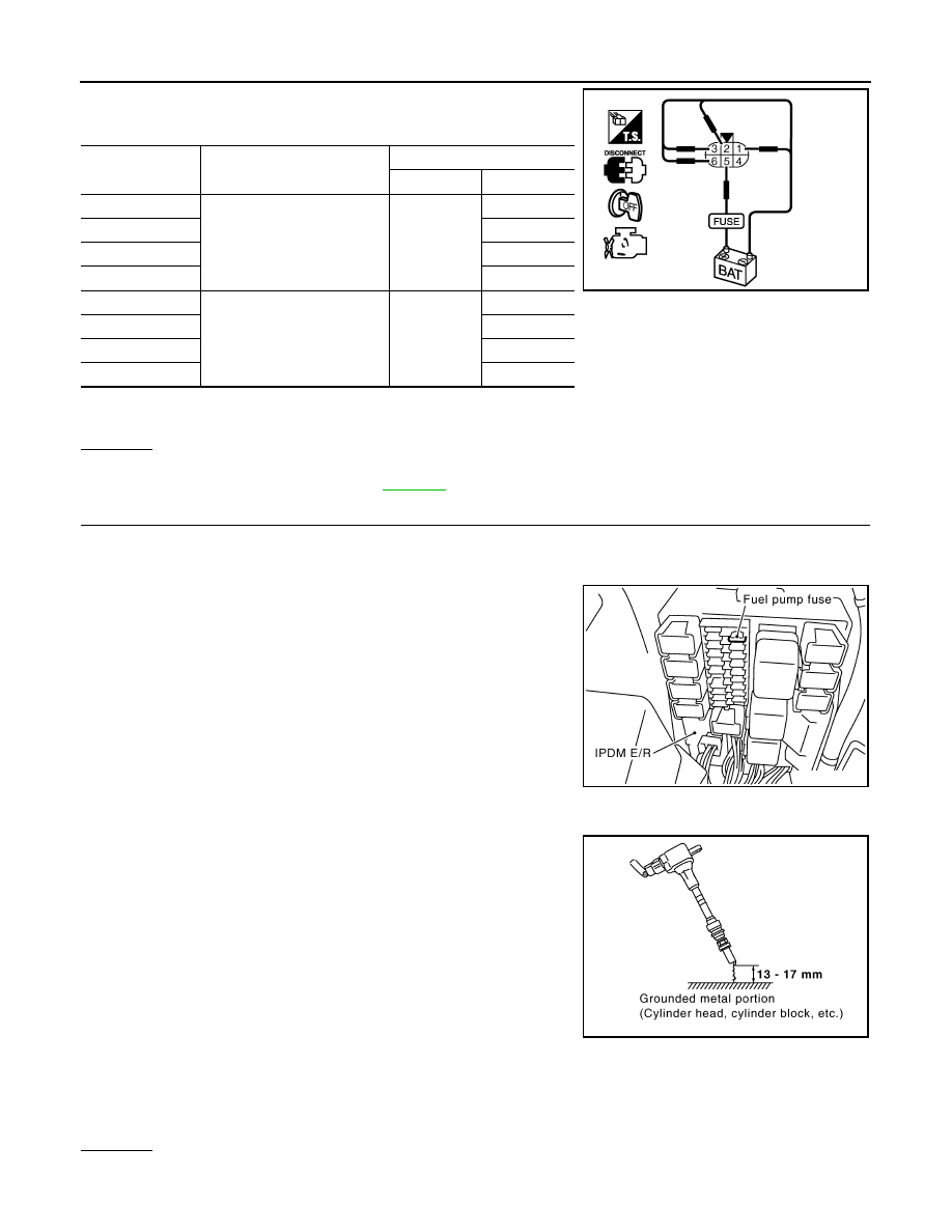
Provide battery voltage between the following terminals, and then
interrupt it. Listen to each fuel injector operating sound.
OK or NG
OK
>> GO TO 6.
NG
>> Perform trouble diagnosis for
.
6.
CHECK FUNCTION OF IGNITION COIL-I
CAUTION:
Do the following procedure in the place where ventilation is good without the combustible.
1.
Turn ignition switch OFF.
2.
Remove fuel pump fuse in IPDM E/R to release fuel pressure.
NOTE:
Do not use CONSULT-III to release fuel pressure, or fuel pres-
sure applies again during the following procedure.
3.
Start engine.
4.
After engine stalls, crank it two or three times to release all fuel
pressure.
5.
Turn ignition switch OFF.
6.
Remove all ignition coil harness connectors to avoid the electri-
cal discharge from the ignition coils.
7.
Remove ignition coil and spark plug of the cylinder to be
checked.
8.
Crank engine for five seconds or more to remove combustion gas in the cylinder.
9.
Connect spark plug and harness connector to ignition coil.
10. Fix ignition coil using a rope etc. with gap of 13 - 17 mm
between the edge of the spark plug and grounded metal portion
as shown in the figure.
11. Crank engine for about three seconds, and check whether spark
is generated between the spark plug and the grounded metal
portion.
CAUTION:
• Do not approach to the spark plug and the ignition coil
within 50cm. Be careful not to get an electrical shock
while checking, because the electrical discharge voltage
becomes 20kV or more.
• It might cause to damage the ignition coil if the gap of more than 17 mm is taken.
NOTE:
When the gap is less than 13 mm, the spark might be generated even if the coil is malfunctioning.
OK or NG
OK
>> GO TO 10.
Cylinder
Harness connector
terminal
(+)
(–)
1
F201
5
3
3
2
5
1
7
6
2
F221
5
3
4
2
6
1
8
6
Operating sound should exist.
PBIB2449E
Spark should be generated.
PBIB1482E
PBIB2325E
DTC P0300 - P0308 MULTIPLE CYLINDER MISFIRE, NO. 1 - 8 CYLINDER MIS-
FIRE
EC-899
< SERVICE INFORMATION >
[VK45DE]
C
D
E
F
G
H
I
J
K
L
M
A
EC
N
P
O
NG
>> GO TO 7.
7.
CHECK FUNCTION OF IGNITION COIL-II
1.
Turn ignition switch OFF.
2.
Disconnect spark plug and connect a known-good spark plug.
3.
Crank engine for about three seconds, and recheck whether spark is generated between the spark plug
and the grounded metal portion.
OK or NG
OK
>> GO TO 8.
NG
>> Check ignition coil, power transistor and their circuits. Refer to
.
8.
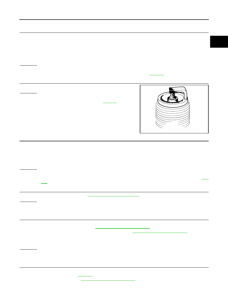
CHECK SPARK PLUG
Check the initial spark plug for fouling, etc.
OK or NG
OK
>> Replace malfunctioning spark plug(s) with standard type
one(s). For spark plug type, refer to
.
NG
>> 1.
Repair or clean spark plug.
2.
GO TO 9.
9.
CHECK FUNCTION OF IGNITION COIL-III
1.
Reconnect the initial spark plugs.
2.
Crank engine for about three seconds, and recheck whether spark is generated between the spark plug
and the grounded portion.
OK or NG
OK
>> INSPECTION END
NG
>> Replace malfunctioning spark plug(s) with standard type one(s). For spark plug type, refer to
.
10.
CHECK COMPRESSION PRESSURE
Check compression pressure. Refer to
OK or NG
OK
>> GO TO 11.
NG
>> Check pistons, piston rings, valves, valve seats and cylinder head gaskets.
11.
CHECK FUEL PRESSURE
1.
Install all removed parts.
2.
Release fuel pressure to zero. Refer to
3.
Install fuel pressure gauge and check fuel pressure. Refer to
OK or NG
OK
>> GO TO 13.
NG
>> GO TO 12.
12.
DETECT MALFUNCTIONING PART
Check the following.
• Fuel pump and circuit (Refer to
• Fuel pressure regulator (Refer to
Spark should be generated.
SEF156I
Spark should be generated.
At idling:
Approximately 350 kPa (3.57 kg/cm
2
, 51 psi)
EC-900
< SERVICE INFORMATION >
[VK45DE]
DTC P0300 - P0308 MULTIPLE CYLINDER MISFIRE, NO. 1 - 8 CYLINDER MIS-
FIRE
• Fuel lines (Refer to
• Fuel filter for clogging
>> Repair or replace.
13.
CHECK IGNITION TIMING
Check the following items. Refer to
OK or NG
OK
>> GO TO 14.
NG
>> Follow the Basic Inspection.
14.
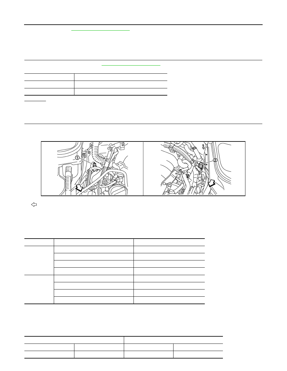
CHECK AIR FUEL RATIO (A/F) SENSOR 1 INPUT SIGNAL CIRCUIT
1.
Turn ignition switch OFF.
2.
Disconnect air fuel ratio (A/F) sensor 1 harness connector.
3.
Disconnect ECM harness connector.
4.
Check harness continuity between the following terminals.
Refer to Wiring Diagram.
5.
Check harness continuity between the following terminals and ground.
Refer to Wiring Diagram.
Items
Specifications
Target idle speed
650
±
50 rpm (in P or N position)
Ignition timing
12
±
5
°
BTDC (in P or N position)
: Vehicle front
1.
A/F sensor 1 (Bank 2)
harness connector
2.
A/F sensor 1 (Bank 1)
harness connector
A/F sensor 1 terminal
ECM terminal
Bank 1
1
16
2
75
5
35
6
56
Bank 2
1
76
2
77
5
57
6
58
Continuity should exist.
Bank 1
Bank 2
A/F sensor 1 terminal
ECM terminal
A/F sensor 1 terminal
ECM terminal
1
16
1
76
PBIB3246E
Нет комментариевНе стесняйтесь поделиться с нами вашим ценным мнением.
Текст