Infiniti FX35 / FX45. Manual — part 905
SC-8
< SERVICE INFORMATION >
STARTING SYSTEM
STARTING SYSTEM
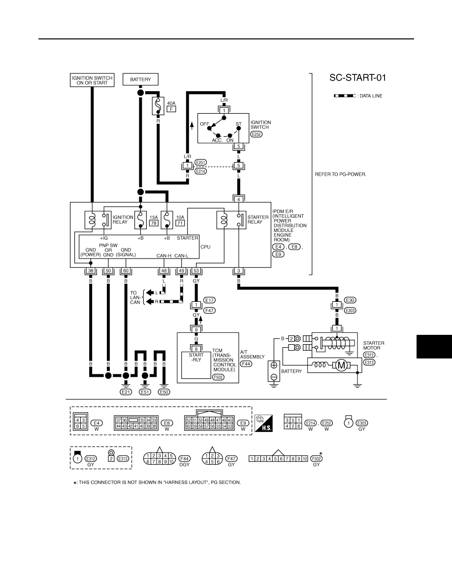
System Description
INFOID:0000000001328246
Power is supplied at all times
• through 40A fusible link (letter F, located in the fuse and fusible link block)
• to ignition switch terminal 1,
• through 15A fuse (No. 78, located in the IPDM E/R)
• to CPU of IPDM E/R,
• through 10A fuse (No. 71, located in the IPDM E/R)
• to CPU of IPDM E/R.
When the selector lever in the P or N position, power is supplied
• from TCM, and through A/T assembly terminal 9
• to IPDM E/R terminal 53.
Ground is supplied
• to IPDM E/R terminals 38, 50 and 60
• from grounds E21, E50 and E51.
With the ignition switch in the START position, and provided that the IPDM E/R receives a starter relay ON sig-
nal from the CAN lines, the IPDM E/R is energized and power is supplied
• from ignition switch terminal 5
• to IPDM E/R terminal 4 and
• through IPDM E/R terminal 3
• to starter motor terminal 1.
The starter motor plunger closes and provides a closed circuit between the battery and starter motor. The
starter motor is grounded to the engine block. With power and ground supplied, cranking occurs and the
engine starts.
STARTING SYSTEM
SC-9
< SERVICE INFORMATION >
C
D
E
F
G
H
I
J
L
M
A
B
SC
N
O
P
Wiring Diagram - START -
INFOID:0000000001328247
VK45DE ENGINE MODELS
TKWM1275E
SC-10
< SERVICE INFORMATION >
STARTING SYSTEM
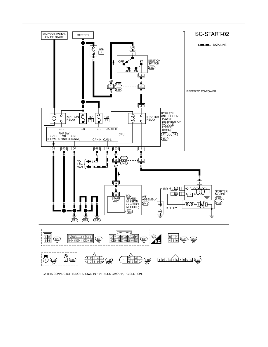
VQ35DE ENGINE MODELS
Trouble Diagnosis with Starting/Charging System Tester (Starting)
INFOID:0000000001328248
For starting system testing, use Starting/Charging System Tester (J-44373). For details and operating instruc-
tions, refer to Technical Service Bulletin.
TKWM1276E
STARTING SYSTEM
SC-11
< SERVICE INFORMATION >
C
D
E
F
G
H
I
J
L
M
A
B
SC
N
O
P
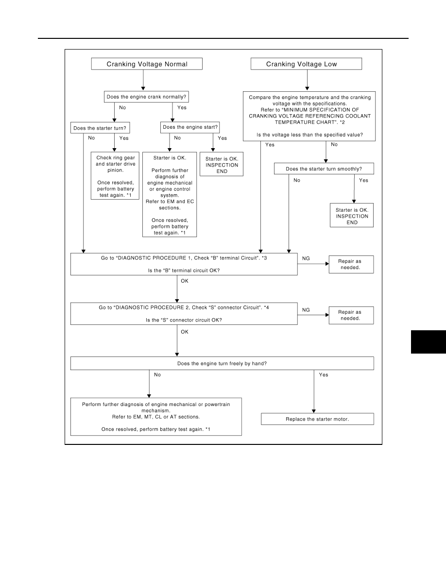
DIAGNOSTIC PROCEDURE 1
Check “B” Terminal Circuit
CAUTION:
Perform diagnosis under the condition that engine cannot start by the following procedure.
*1
For battery testing, use Battery Ser-
vice Center (J-48087). For details
and operating instructions, refer to
Technical Service Bulletin and/or Bat-
tery Service Center User Guide.
*2
Refer to "MINIMUM SPECIFICA-
TION OF CRANKING VOLTAGE
REFERENCING COOLANT TEM-
PERATURE".
*3
Refer to "Check “B” Terminal Circuit".
*4
Refer to "Check “S” Connector Cir-
cuit".
SKIB1369E
Нет комментариевНе стесняйтесь поделиться с нами вашим ценным мнением.
Текст