Infiniti FX35 / FX45. Manual — part 906
SC-12
< SERVICE INFORMATION >
STARTING SYSTEM
1.
Remove fuel pump fuse.
2.
Crank or start the engine (where possible) until the fuel pressure is released.
1.
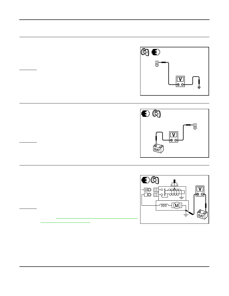
CHECK “B” TERMINAL CIRCUIT
1.
Turn ignition switch OFF.
2.
Make sure that starter motor “B” terminal E313 terminal 2 connection is clean and tight.
3.
Check voltage between starter motor “B” terminal E313 terminal
2 and ground.
OK or NG
OK
>> GO TO 2.
NG
>> Check harness between battery and starter motor for
open circuit.
2.
CHECK BATTERY CABLE CONNECTION STATUS (VOLTAGE DROP TEST)
1.
Shift A/T selector lever to “P” or “N” position.
2.
Check voltage between starter motor “B” terminal E313 terminal
2 and battery positive terminal.
OK or NG
OK
>> GO TO 3.
NG
>> Check harness between battery and starter motor for
poor continuity.
3.
CHECK GROUND CIRCUIT STATUS (VOLTAGE DROP TEST)
1.
Turn ignition switch OFF.
2.
Shift A/T selector lever to “P” or “N” position.
3.
Check voltage between starter motor case and battery negative
terminal.
OK or NG
OK
>> “B” terminal circuit is OK. Further inspection necessary.
Refer to
SC-10, "Trouble Diagnosis with Starting/Charg-
NG
>> Check starter motor case and ground for poor continuity.
DIAGNOSTIC PROCEDURE 2
Check “S” Connector Circuit
CAUTION:
Perform diagnosis under the condition that engine cannot start by the following procedure.
1.
Remove fuel pump fuse.
2.
Crank or start the engine (where possible) until the fuel pressure is released.
1.
CHECK “S” CONNECTOR CIRCUIT
1.
Turn ignition switch OFF.
2.
Disconnect starter motor connector.
3.
Shift A/T selector lever to “P” or “N” position.
2 – Ground
: Battery voltage
PKIB8793E
2 – Battery positive terminal
When ignition switch is in START
position
: Less than 0.5 V
PKIB8794E
Starter motor case – Battery negative terminal
When ignition switch is in
START position
: Less than 0.2 V
PKIB8795E
STARTING SYSTEM
SC-13
< SERVICE INFORMATION >
C
D
E
F
G
H
I
J
L
M
A
B
SC
N
O
P
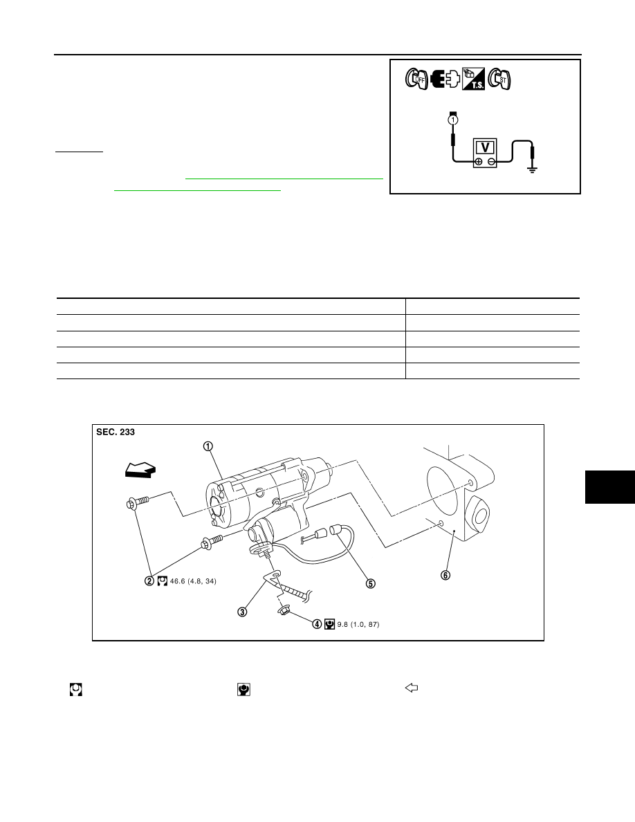
4.
Check voltage between starter motor harness connector E312
(VK45DE) or F33 (VQ35DE) terminal 1 and ground.
OK or NG
OK
>> “S” connector circuit is OK. Further inspection neces-
sary. Refer to
SC-10, "Trouble Diagnosis with Starting/
Charging System Tester (Starting)"
.
NG
>>
Check the following.
• 40A fusible link (letter F, located in fuse and fusible link box)
• Ignition switch
• Starter relay (within the IPDM E/R)
• Harness for open or short
MINIMUM SPECIFICATION OF CRANKING VOLTAGE REFERENCING COOLANT TEMPERA-
TURE
Removal and Installation (VK45DE Engine Models)
INFOID:0000000001328249
REMOVAL
1.
Disconnect the battery cable from the negative terminal.
2.
Remove engine front and rear undercover, using power tools.
1 – Ground
When ignition switch is in
START position
: Battery voltage
PKIB8796E
Engine coolant temperature
Voltage [V]
−
30
°
C to
−
20
°
C (
−
22
°
F to
−
4
°
F)
8.4
−
19
°
C to
−
10
°
C (
−
2
°
F to 14
°
F)
8.9
−
9
°
C to 0
°
C (16
°
F to 32
°
F)
9.3
More than 1
°
C (More than 34
°
F)
9.7
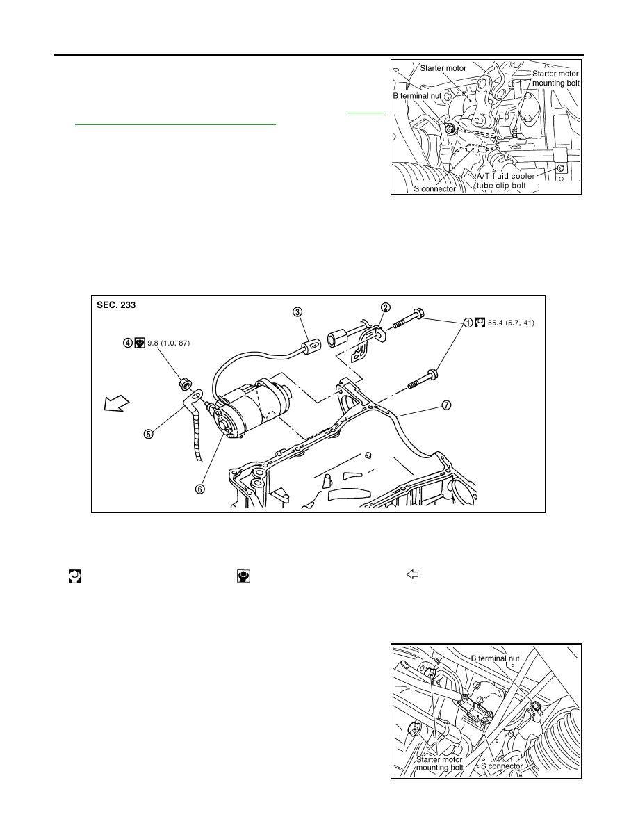
1.
Starter motor
2.
Starter motor mounting bolt
3.
B terminal harness
4.
B terminal nut
5.
S connector
6.
Cylinder block
: N·m (kg-m, ft-lb)
: N·m (kg-m, ft-in)
: Engine front
PKID1545E
SC-14
< SERVICE INFORMATION >
STARTING SYSTEM
3.
Disconnect “S” connector.
4.
Remove “B” terminal nut.
5.
Remove starter motor mounting bolts.
6.
Loosen A/T fluid cooler tube clip bolts. Refer to
"Removal and Installation (AWD Models)"
7.
Remove starter motor downward from the vehicle.
INSTALLATION
Installation is the reverse order of removal.
CAUTION:
Be sure to tighten “B” terminal nut carefully.
Removal and Installation [VQ35DE Engine Models (2WD)]
INFOID:0000000001328250
REMOVAL
1.
Disconnect the battery cable from the negative terminal.
2.
Remove engine rear undercover, using power tools.
3.
Disconnect “S” connector.
4.
Remove “B” terminal nut.
5.
Remove starter motor mounting bolts and harness clip bracket,
using power tools.
6.
Remove starter motor downward from the vehicle.
PKIA2810E
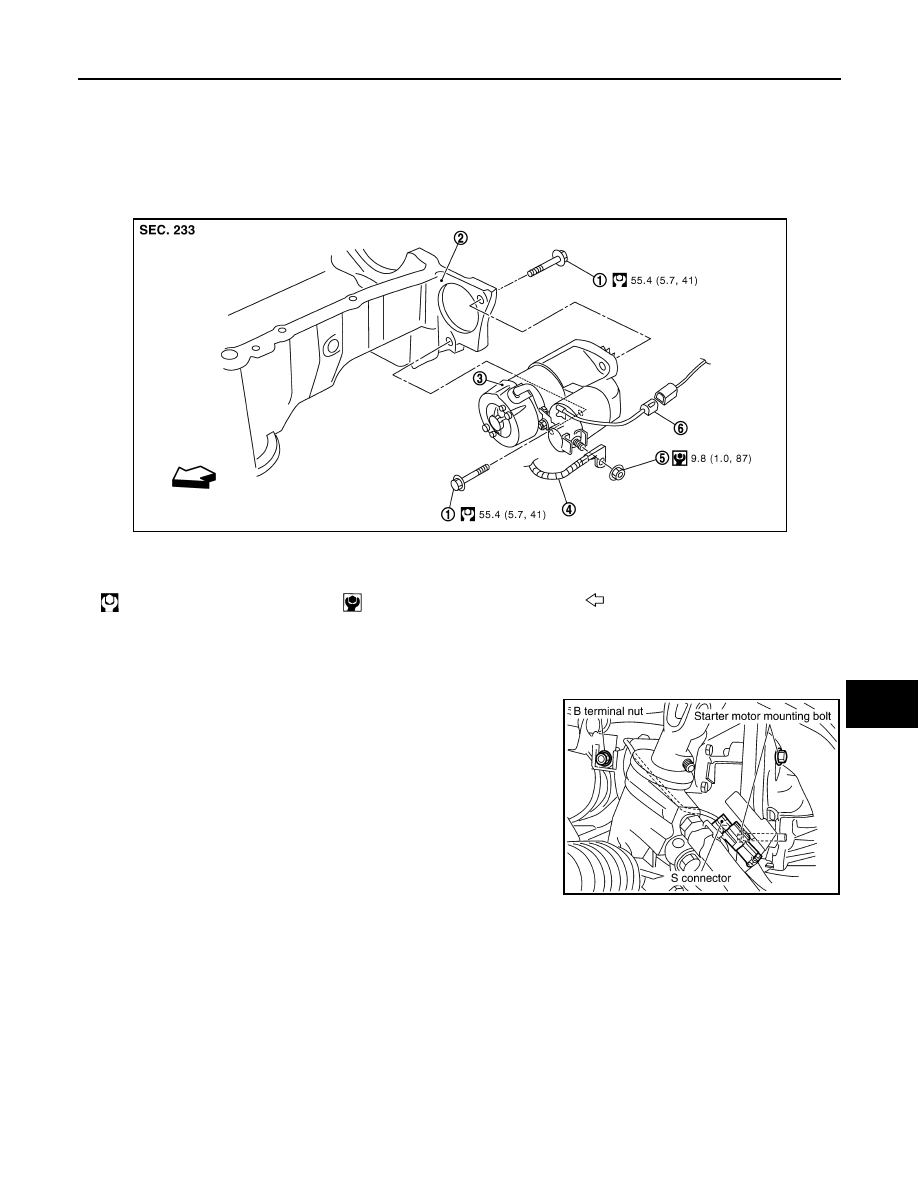
1.
Starter motor mounting bolt
2.
Harness clip bracket
3.
S connector
4.
B terminal nut
5.
B terminal harness
6.
Starter motor
7.
Oil pan
: N·m (kg-m, ft-lb)
: N·m (kg-m, ft-in)
: Engine front
PKIB8799E
PKIA2812E
STARTING SYSTEM
SC-15
< SERVICE INFORMATION >
C
D
E
F
G
H
I
J
L
M
A
B
SC
N
O
P
INSTALLATION
Installation is the reverse order of removal.
CAUTION:
Be sure to tighten “B” terminal nut carefully.
Removal and Installation [VQ35DE Engine Models (AWD)]
INFOID:0000000001328251
REMOVAL
1.
Disconnect the battery cable from the negative terminal.
2.
Remove engine front and rear undercover, using power tools.
3.
Disconnect “S” connector.
4.
Remove “B” terminal nut.
5.
Remove starter motor mounting bolts.
6.
Remove starter motor downward from the vehicle.
INSTALLATION
Installation is the reverse order of removal.
CAUTION:
Be sure to tighten “B” terminal nut carefully.
Disassembly and Assembly
INFOID:0000000001328252
VK45DE ENGINE MODELS (M002T85075)
1.
Starter motor mounting bolt
2.
Oil pan
3.
Starter motor
4.
B terminal harness
5.
B terminal nut
6.
S connector
: N·m (kg-m, ft-lb)
: N·m (kg-m, ft-in)
: Engine front
PKID1546E
PKIA2844E
Нет комментариевНе стесняйтесь поделиться с нами вашим ценным мнением.
Текст