Infiniti FX35 / FX45. Manual — part 528
DTC P0172, P0175 FUEL INJECTION SYSTEM FUNCTION
EC-873
< SERVICE INFORMATION >
[VK45DE]
C
D
E
F
G
H
I
J
K
L
M
A
EC
N
P
O
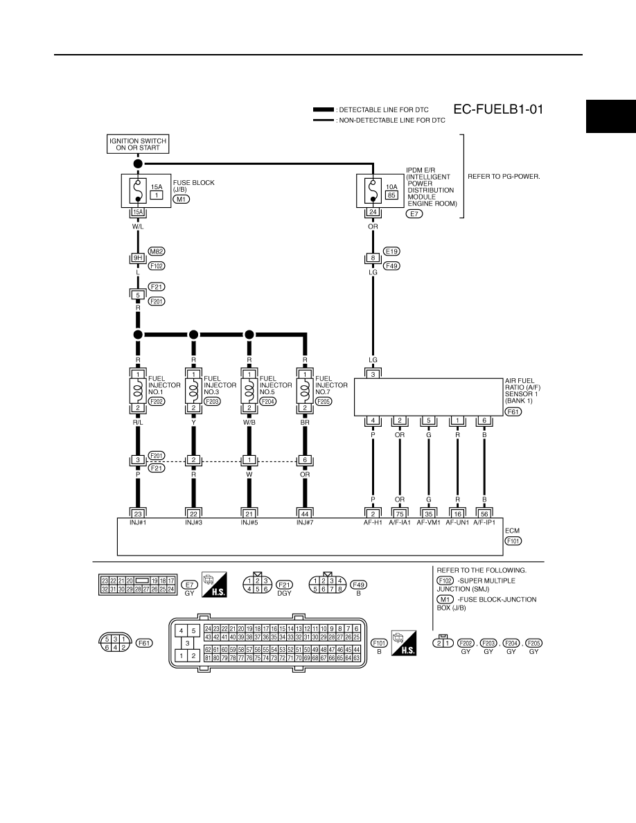
Wiring Diagram
INFOID:0000000001326704
BANK 1
Specification data are reference values and are measured between each terminal and ground.
Pulse signal is measured by CONSULT-III.
CAUTION:
TBWM1332E
EC-874
< SERVICE INFORMATION >
[VK45DE]
DTC P0172, P0175 FUEL INJECTION SYSTEM FUNCTION
Do not use ECM ground terminals when measuring input/output voltage. Doing so may result in dam-
age to the ECM's transistor. Use a ground other than ECM terminals, such as the ground.
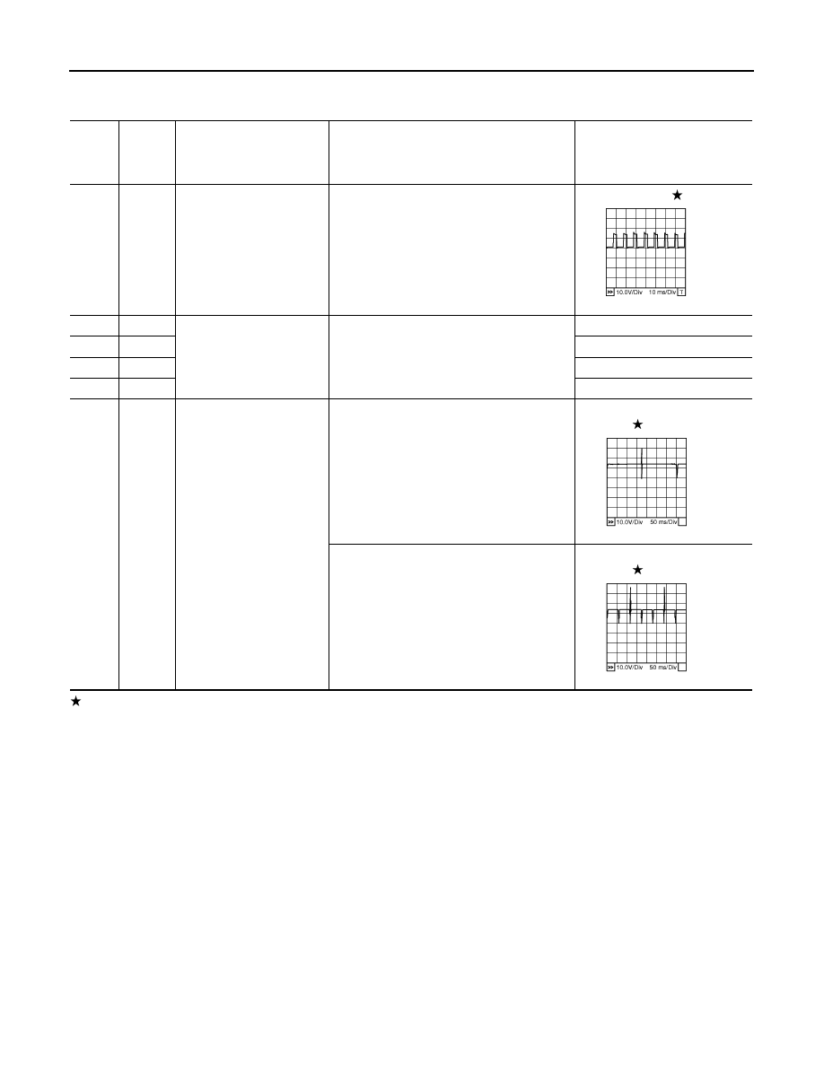
: Average voltage for pulse signal (Actual pulse signal can be confirmed by oscilloscope.)
TER-
MI-
NAL
NO.
WIRE
COLOR
ITEM
CONDITION
DATA (DC Voltage)
2
P
A/F sensor 1 heater
(Bank 1)
[Engine is running]
• Warm-up condition
• Idle speed
Approximately 5V
16
R
A/F sensor 1 (Bank 1)
[Engine is running]
• Warm-up condition
• Idle speed
Approximately 3.1V
35
G
Approximately 2.6V
56
B
Approximately 2.3V
75
OR
Approximately 2.3V
21
22
23
44
W
R
P
OR
Fuel injector No. 5
Fuel injector No. 3
Fuel injector No. 1
Fuel injector No. 7
[Engine is running]
• Warm-up condition
• Idle speed
NOTE:
The pulse cycle changes depending on rpm
at idle
BATTERY VOLTAGE
(11 - 14V)
[Engine is running]
• Warm-up condition
• Engine speed: 2,000 rpm
BATTERY VOLTAGE
(11 - 14V)
PBIB1584E
PBIB0042E
PBIB0043E
DTC P0172, P0175 FUEL INJECTION SYSTEM FUNCTION
EC-875
< SERVICE INFORMATION >
[VK45DE]
C
D
E
F
G
H
I
J
K
L
M
A
EC
N
P
O
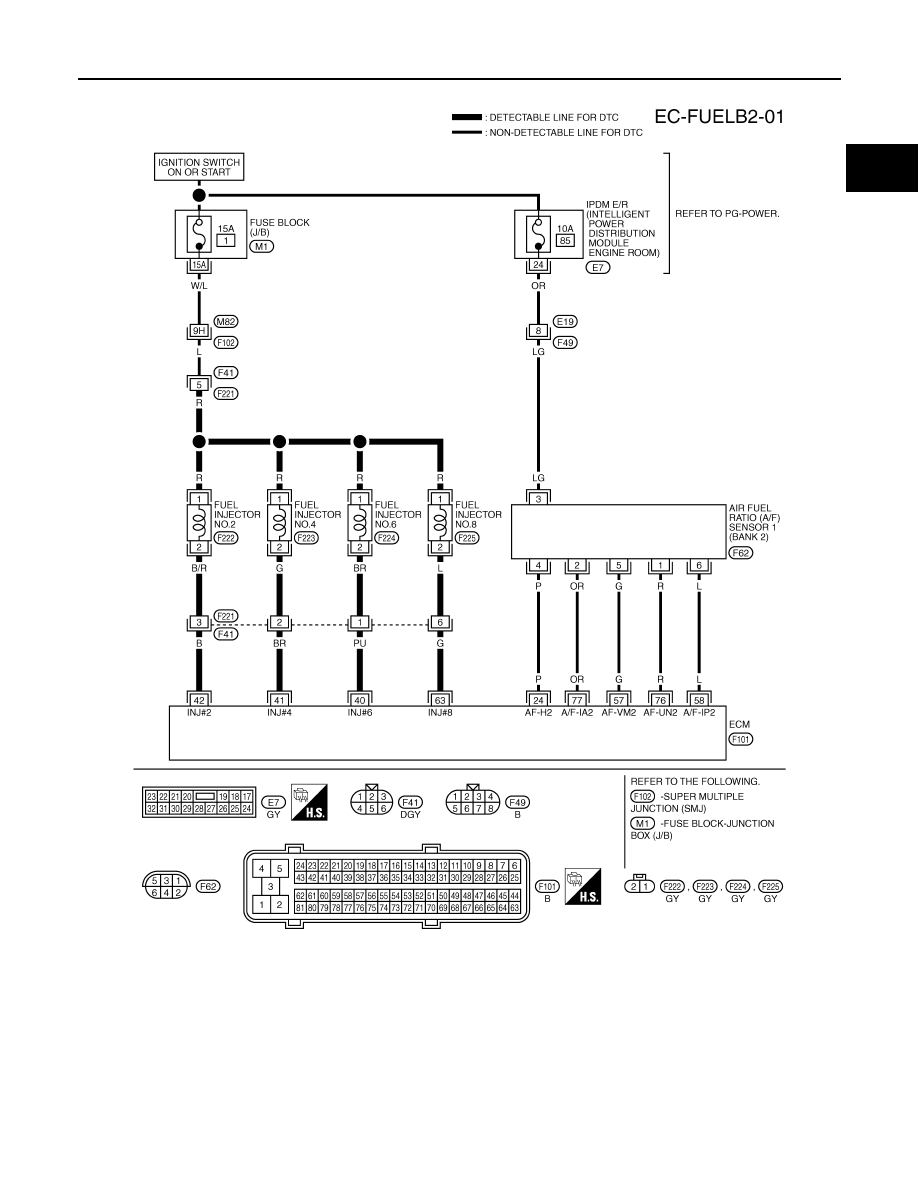
BANK 2
Specification data are reference values and are measured between each terminal and ground.
Pulse signal is measured by CONSULT-III.
CAUTION:
Do not use ECM ground terminals when measuring input/output voltage. Doing so may result in dam-
age to the ECM's transistor. Use a ground other than ECM terminals, such as the ground.
TBWM1333E

EC-876
< SERVICE INFORMATION >
[VK45DE]
DTC P0172, P0175 FUEL INJECTION SYSTEM FUNCTION
: Average voltage for pulse signal (Actual pulse signal can be confirmed by oscilloscope.)
Diagnosis Procedure
INFOID:0000000001326705
1.
CHECK EXHAUST GAS LEAK
1.
Start engine and run it at idle.
2.
Listen for an exhaust gas leak before three way catalyst (manifold).
OK or NG
OK
>> GO TO 2.
NG
>> Repair or replace.
2.
CHECK FOR INTAKE AIR LEAK
TER-
MI-
NAL
NO.
WIRE
COLOR
ITEM
CONDITION
DATA (DC Voltage)
24
P
A/F sensor 1 heater
(Bank 2)
[Engine is running]
• Warm-up condition
• Idle speed
Approximately 5V
40
41
42
63
PU
BR
B
G
Fuel injector No. 6
Fuel injector No. 4
Fuel injector No. 2
Fuel injector No. 8
[Engine is running]
• Warm-up condition
• Idle speed
NOTE:
The pulse cycle changes depending on rpm
at idle
BATTERY VOLTAGE
(11 - 14V)
[Engine is running]
• Warm-up condition
• Engine speed: 2,000 rpm
BATTERY VOLTAGE
(11 - 14V)
57
G
A/F sensor 1 (Bank 2)
[Engine is running]
• Warm-up condition
• Idle speed
Approximately 2.6V
58
L
Approximately 2.3V
76
R
Approximately 3.1V
77
OR
Approximately 2.3V
PBIB1584E
PBIB0042E
PBIB0043E
PBIB1216E
Нет комментариевНе стесняйтесь поделиться с нами вашим ценным мнением.
Текст