Infiniti FX35 / FX45. Manual — part 650
ENGINE ASSEMBLY
EM-117
< SERVICE INFORMATION >
[VQ35DE]
C
D
E
F
G
H
I
J
K
L
M
A
EM
N
P
O
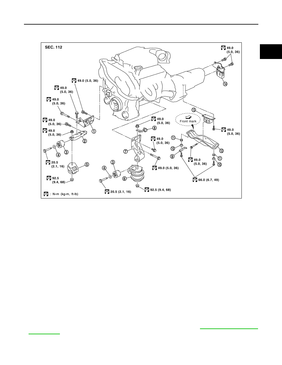
Component (AWD Models)
INFOID:0000000001325744
Removal and Installation (AWD Models)
INFOID:0000000001325745
WARNING:
• Situate the vehicle on a flat and solid surface.
• Place chocks at front and back of rear wheels.
• For engines not equipped with engine slingers, attach proper slingers and bolts described in PARTS
CATALOG.
CAUTION:
• Always be careful to work safely, avoid forceful or uninstructed operations.
• Do not start working until exhaust system and engine coolant are cool enough.
• If items or work required are not covered by the engine section, refer to the applicable sections.
• Always use the support point specified for lifting.
• Use either 2-pole lift type or separate type lift as best you can. If board-on type is used for unavoid-
able reasons, support at rear axle jacking point with transmission jack or similar tool before starting
work, in preparation for the backward shift of center of gravity.
• For supporting points for lifting and jacking point at rear axle, refer to
REMOVAL
Outline
1.
Engine mounting bracket (RH)
2.
Engine mounting bracket (RH) (Low-
er)
3.
Dynamic damper
4.
Washer
5.
Engine mounting insulator (RH)
6.
Engine mounting insulator (LH)
7.
Engine mounting bracket (LH)
8.
Harness bracket
9.
Heat insulator
10.
Caller
11.
Rubber bush
12. Rear engine mounting member
13.
Engine mounting insulator (rear)
14.
Dynamic damper
PBIC3041E
EM-118
< SERVICE INFORMATION >
[VQ35DE]
ENGINE ASSEMBLY
At first, remove the engine, the transmission assembly, the transfer assembly and the front final drive assem-
bly with front suspension member downward. Then separate the engine, the transmission assembly, the trans-
fer and the front final drive assembly.
Preparation
1.
Release fuel pressure. Refer to
2.
Drain engine coolant from radiator. Refer to
CO-10, "Changing Engine Coolant"
.
CAUTION:
• Perform this step when engine is cold.
• Do not spill engine coolant on drive belts.
3.
Disconnect both battery terminals. Refer to
4.
Remove the following parts:
• Engine cover: Refer to
• Front road wheel and tires
• Front and rear engine undercover
• Front cross bar: Refer to
FSU-16, "Removal and Installation"
• Cowl top cover (right): Refer to
EI-23, "Component Parts Location"
• Air duct and air cleaner case assembly:
.
5.
Discharge refrigerant from A/C circuit. Refer to
ATC-120, "HFC-134a (R-134a) Service Procedure"
6.
Remove radiator hoses (upper and lower). Refer to
Engine Room
1.
Disconnect heater hose from vehicle-side, and fit a plug onto hose end to prevent engine coolant leak.
2.
Disconnect grounding cable (between vehicle to left bank cylinder head).
3.
Disconnect battery positive cable harness at vehicle side and temporarily fasten it on engine.
4.
Disconnect A/C piping from A/C compressor, and temporarily fasten it on vehicle with a rope. Refer to
ATC-120, "HFC-134a (R-134a) Service Procedure"
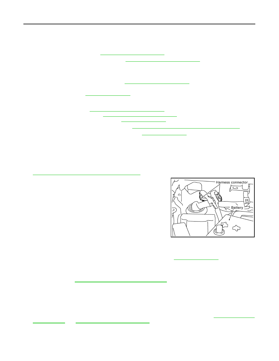
5.
Disconnect engine room harness connectors shown in the fig-
ure.
6.
Disconnect two body ground cables.
7.
Disconnect brake booster vacuum hose.
8.
Disconnect fuel feed hose (with damper) and EVAP hose. Refer to
CAUTION:
Fit plugs onto disconnected hoses to prevent fuel leak.
9.
Remove reservoir tank of power steering oil pump and piping from vehicle, and temporarily secure them
on engine. Refer to
PS-27, "On-Vehicle Inspection and Service"
.
CAUTION:
When temporarily securing, keep the reservoir tank upright to avoid a fluid leak.
Passenger Room Side
Follow procedure below to disconnect engine room harness connectors at passenger room side, and tempo-
rarily secure them on engine.
1.
Remove passenger-side kicking plate, dash side finisher, and glove box. Refer to
IP-10, "Component Parts Location"
SBIA0472E
ENGINE ASSEMBLY
EM-119
< SERVICE INFORMATION >
[VQ35DE]
C
D
E
F
G
H
I
J
K
L
M
A
EM
N
P
O
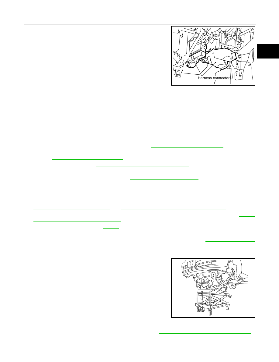
2.
Disconnect engine room harness connectors at unit sides TCM,
ECM and other.
3.
Disengage intermediate fixing point. Pull out engine room harnesses to engine room side, and temporarily
secure them on engine.
CAUTION:
• When pulling out harnesses, take care not to damage harnesses and connectors.
• After temporarily securing, cover connectors with vinyl or similar material to protect against for-
eign material adhesion.
Vehicle Underbody
1.
Remove A/T fluid cooler hoses and power steering oil pump oil cooler hoses.
• Install plug to avoid leakage of A/T fluid and power steering fluid.
2.
Remove exhaust front tube and center muffler. Refer to
EX-3, "Checking Exhaust System"
.
3.
Disconnect steering lower joint at power steering gear assembly side, and release steering lower shaft.
Refer to
PS-12, "Removal and Installation"
.
4.
Remove tunnel stay. Refer to
RSU-5, "On-Vehicle Inspection and Service"
.
5.
Remove rear propeller shaft. Refer to
6.
Remove front drive shaft (both side). Refer to
FAX-13, "On-Vehicle Inspection"
.
7.
Disconnect harness connector from transmission assembly and transfer assembly.
8.
Disengage A/T control rod at control device assembly side. Then, temporarily secure it on the transmis-
sion assembly, so that it does not sag. Refer to
AT-205, "Control Device Removal and Installation"
9.
Remove rear plate from oil pan (upper). Then remove bolts fixing drive plate to torque converter. Refer to
EM-30, "Component (2WD Models)"
AT-241, "Removal and Installation (2WD Models)"
10. Remove bolts fixing the transmission assembly to lower rear side of oil pan (upper). Refer to
"Removal and Installation (2WD Models)"
.
11. Remove front stabilizer. Refer to
.
12. Separate steering outer sockets from steering knuckle. Refer to
PS-17, "Removal and Installation"
13. Separate transverse links from suspension member and vehicle body. Refer to
.
Removal Work
1.
Use a manual lift table caddy (commercial service tool) or equiv-
alently rigid tool such as a transmission jack. Securely support
bottom of suspension member and transmission.
CAUTION:
Put a piece of wood or something similar as the supporting
surface, secure a completely stable condition.
2.
Remove rear engine mounting member bolts.
3.
Remove front suspension member mounting nuts. Refer to
FSU-5, "On-Vehicle Inspection and Service"
4.
Carefully lower jack, or raise lift to remove the engine, transmission assembly, transfer, front final drive
assembly and front suspension member. When performing work, observe the following caution:
SBIA0473E
PBIC0804E
EM-120
< SERVICE INFORMATION >
[VQ35DE]
ENGINE ASSEMBLY
CAUTION:
• Confirm there is no interference with the vehicle.
• Make sure that all connection points have been disconnected.
• Keep in mind the center of the vehicle gravity changes. If necessary, use jack(s) to support the
vehicle at rear jacking point(s) to prevent it from falling it off the lift.
Separation Work
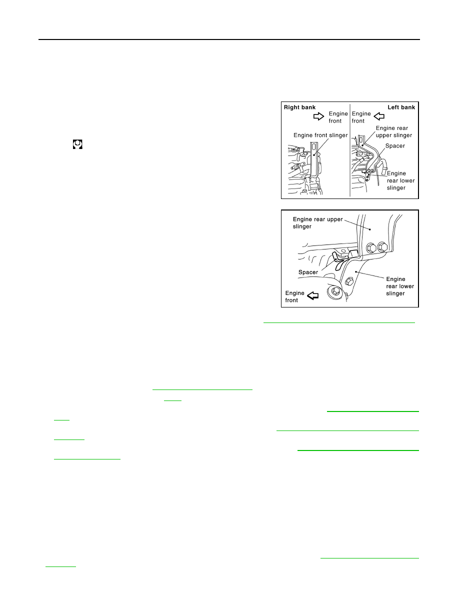
1.
Install engine slingers into front of cylinder head (right bank) and
rear of cylinder head (left bank).
• To protect rocker cover against damage caused by tilting of
engine slinger, insert spacer between cylinder head and
engine rear lower slinger, in direction shown in the figure.
NOTE:
Spacer is a component part of engine rear upper slinger
assembly.
2.
Remove power steering oil pump from engine side. Refer to
PS-27, "On-Vehicle Inspection and Service"
.
3.
Remove engine mounting insulators (RH and LH) under side nuts with power tool.
4.
Lift with hoist and separate the engine, the transmission assembly, the transfer assembly and the front
final drive assembly from front suspension member.
CAUTION:
• Before and during this lifting, always check if any harnesses are left connected.
• Avoid damage to and oil/grease smearing or spills onto engine mounting insulator.
5.
Remove alternator. Refer to
6.
Remove starter motor. Refer to
.
7.
Remove front propeller shaft from the front final drive assembly side. Refer to
8.
Separate the engine from the transmission assembly. Refer to
AT-241, "Removal and Installation (2WD
.
9.
Remove the front final drive assembly from oil pan (upper). Refer to
FFD-14, "Removal and Installation
10. Remove each engine mounting insulator and each engine mounting bracket from the engine with power
tool.
11. Remove rear engine mounting member and engine mounting insulator (rear) from the transmission
assembly.
12. Remove dynamic damper from the transfer assembly.
INSTALLATION
Note the following, and install in the reverse order of removal.
• Do not allow engine mounting insulator to be damage and careful no engine oil gets on it.
• For a location with a positioning pin, insert it securely into hole of mating part.
• For a part with a specified installation orientation, refer to component figure in
.
Slinger bolts:
: 28.0 N·m (2.9 kg-m, 21 ft-lb)
PBIC2061E
KBIA1017E
Нет комментариевНе стесняйтесь поделиться с нами вашим ценным мнением.
Текст