Infiniti FX35 / FX45. Manual — part 651
ENGINE ASSEMBLY
EM-121
< SERVICE INFORMATION >
[VQ35DE]
C
D
E
F
G
H
I
J
K
L
M
A
EM
N
P
O
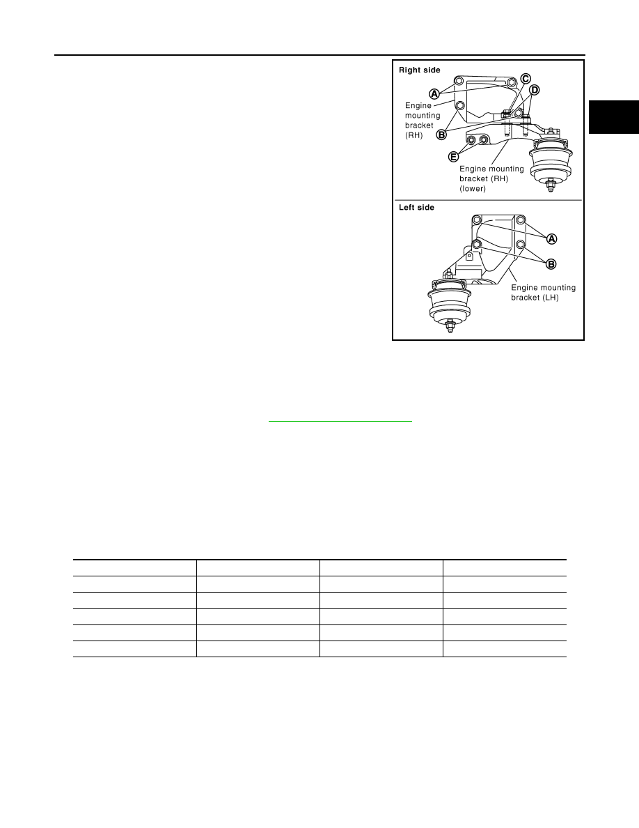
• When installing engine mounting bracket (RH and LH) on cylinder
block, tighten two upper bolts (shown as “A” in the figure) first.
Then tighten two lower bolts (shown as “B” in the figure).
• Install engine mounting bracket (RH) (lower) as follows:
- Temporarily tighten mounting bolts (shown as “C”, “D” and “E” in
the figure).
- Tighten mounting bolts to the specified torque with following
mounting surfaces touched.
• Engine mounting bracket (RH) to engine mounting bracket (RH)
(lower) (shown as “C” and “D” in figure).
• Front final drive to engine mounting bracket (RH) (lower) (shown
as “E” in figure).
• Make sure all engine mounting insulators are seated properly, then
tighten mounting nuts.
INSPECTION AFTER INSTALLATION
Inspection for Leaks
The following are procedures for checking fluids leak, lubricates leak and exhaust gases leak.
• Before starting engine, check oil/fluid levels including engine coolant and engine oil. If less than required
quantity, fill to the specified level. Refer to
.
• Use procedure below to check for fuel leakage.
- Turn ignition switch “ON” (with engine stopped). With fuel pressure applied to fuel piping, check for fuel leak-
age at connection points.
- Start engine. With engine speed increased, check again for fuel leakage at connection points.
• Run engine to check for unusual noise and vibration.
• Warm up engine thoroughly to make sure there is no leakage of fuel, exhaust gases, or any oil/fluids includ-
ing engine oil and engine coolant.
• Bleed air from lines and hoses of applicable lines, such as in cooling system.
• After cooling down engine, again check oil/fluid levels including engine oil and engine coolant. Refill to the
specified level, if necessary.
Summary of the inspection items:
*: Transmission/transaxle/CVT fluid. power steering fluid, brake fluid, etc.
PBIC3042E
Items
Before starting engine
Engine running
After engine stopped
Engine coolant
Level
Leakage
Level
Engine oil
Level
Leakage
Level
Other oils and fluid*
Level
Leakage
Level
Fuel
Leakage
Leakage
Leakage
Exhaust gases
—
Leakage
—
EM-122
< SERVICE INFORMATION >
[VQ35DE]
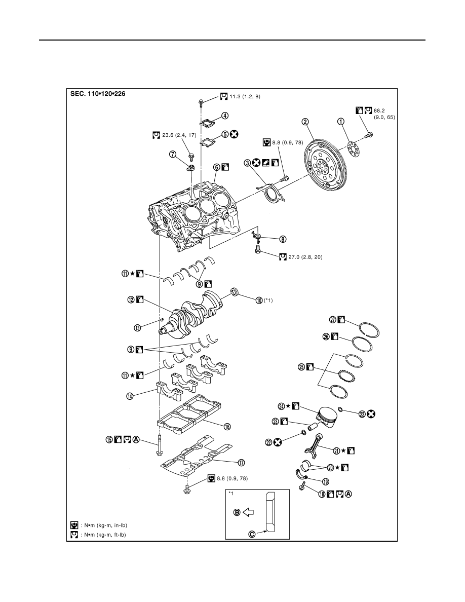
CYLINDER BLOCK
CYLINDER BLOCK
Component
INFOID:0000000001325746
1.
Reinforcement plate
2.
Drive plate
3.
Rear oil seal retainer
4.
Cover
5.
Gasket
6.
Cylinder block
7.
Knock sensor
8.
Oil jet
9.
Thrust bearing
PBIC4690E
CYLINDER BLOCK
EM-123
< SERVICE INFORMATION >
[VQ35DE]
C
D
E
F
G
H
I
J
K
L
M
A
EM
N
P
O
• Refer to
Disassembly and Assembly
INFOID:0000000001325747
DISASSEMBLY
1.
Remove the engine assembly from the vehicle, and separate transmission assembly, transfer assembly
(AWD models), front final drive assembly (AWD models) and front suspension member from the engine.
Refer to
EM-112, "Component (2WD Models)"
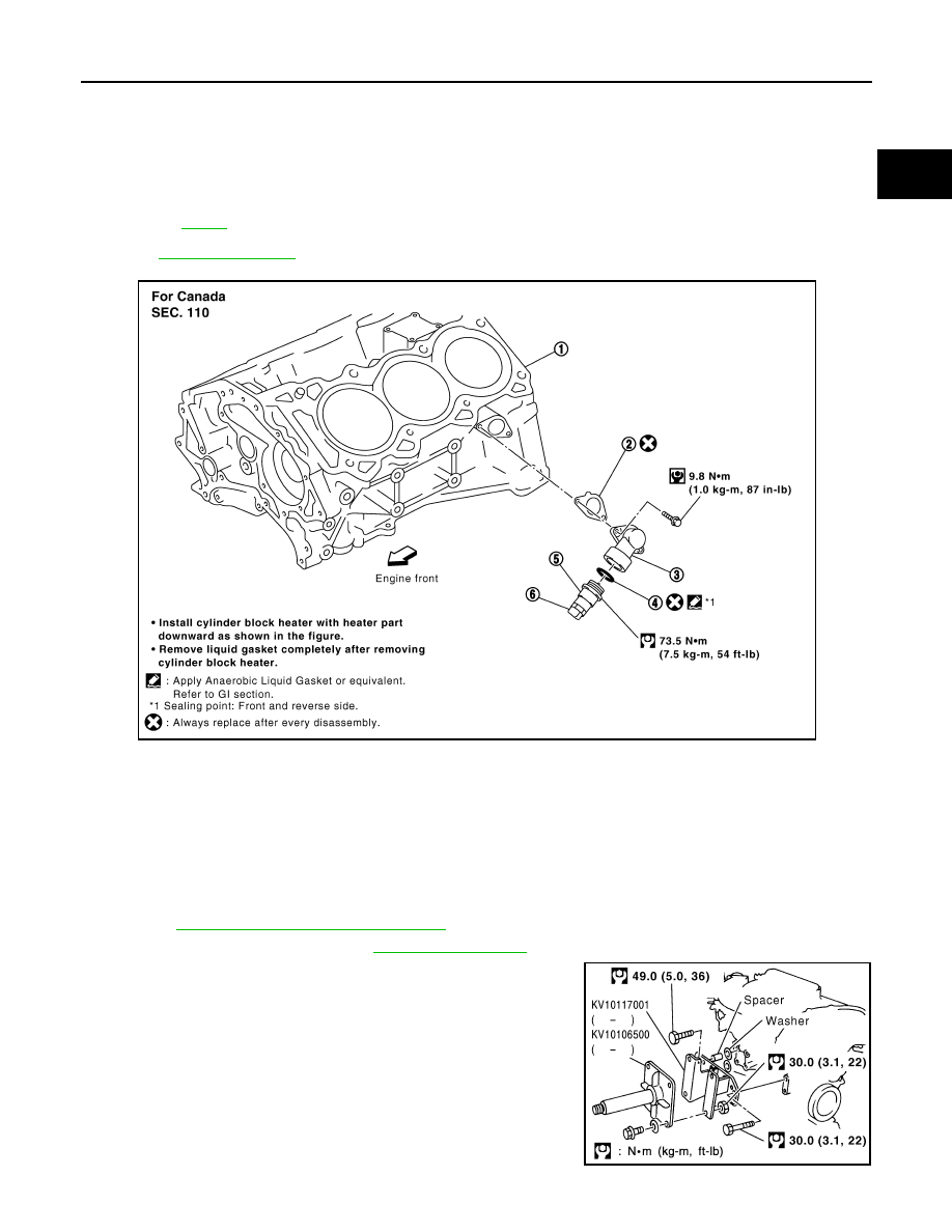
2.
Remove exhaust manifold. Refer to
3.
Install engine sub-attachment with engine stand shaft (SST) to
right side of cylinder block.
• Use a spacer to the engine rear side.
10. Pilot converter
11. Main bearing
12. Crankshaft
13. Crankshaft key
14. Main bearing cap
15. Main bearing cap bolt
16. Main bearing beam
17. Baffle plate (2WD models)
18. Connecting rod bolt
19. Connecting rod bearing cap
20. Connecting rod bearing
21. Connecting rod
22. Snap ring
23. Piston pin
24. Piston
25. Oil ring
26. Second ring
27. Top ring
A.
Refer to
B.
Crankshaft side
C.
Chamfered
1.
Cylinder block
2.
Gasket
3.
Water connector
4.
Gasket
5.
Cylinder block heater
6.
Connector protector cap
PBIC2614E
SBIA0503E

EM-124
< SERVICE INFORMATION >
[VQ35DE]
CYLINDER BLOCK
4.
Lift the engine, and mount it onto engine stand (SST).
• A widely use engine stand can be used.
CAUTION:
Use an engine stand that has a load capacity [approxi-
mately 220 kg (485 lb) or more] large enough for support-
ing the engine weight.
NOTE:
This example is an engine stand for holding at transmission
mounting side with drive plate removed.
5.
Drain engine oil. Refer to
PBIC2685E
PBIC0085E
Нет комментариевНе стесняйтесь поделиться с нами вашим ценным мнением.
Текст