Infiniti FX35 / FX45. Manual — part 784

HEADLAMP - XENON TYPE -
LT-31
< SERVICE INFORMATION >
C
D
E
F
G
H
I
J
L
M
A
B
LT
N
O
P
2.
Turn xenon bulb socket counterclockwise, and unlock it.
3.
Unlock retaining spring, and remove xenon bulb (high/low).
4.
Remove HID control unit cover mounting screw.
5.
Remove HID control unit cover.
6.
Disconnect HID control unit connector.
7.
Remove HID control unit mounting screws.
8.
Remove HID control unit.
9.
Turn daytime/parking lamp bulb socket counterclockwise and unlock it.
10. Remove daytime/parking lamp bulb from its socket.
11. Turn front turn signal lamp bulb socket counterclockwise and unlock it.
12. Remove front turn signal lamp bulb from its socket.
13. Turn front side marker lamp bulb socket counterclockwise and unlock it.
14. Remove front side marker lamp bulb from its socket.
ASSEMBLY
Assembly is the reverse order of disassembly.
CAUTION:
• When HID control unit is removed, reinstall it securely and avoid any looseness.
• After installing bulb, be sure to install plastic cap and bulb socket securely to insure watertightness.
HID control unit mounting screw
: 3.2 N·m (0.33 kg-m, 28 in-lb)
LT-32
< SERVICE INFORMATION >
DAYTIME LIGHT SYSTEM
DAYTIME LIGHT SYSTEM
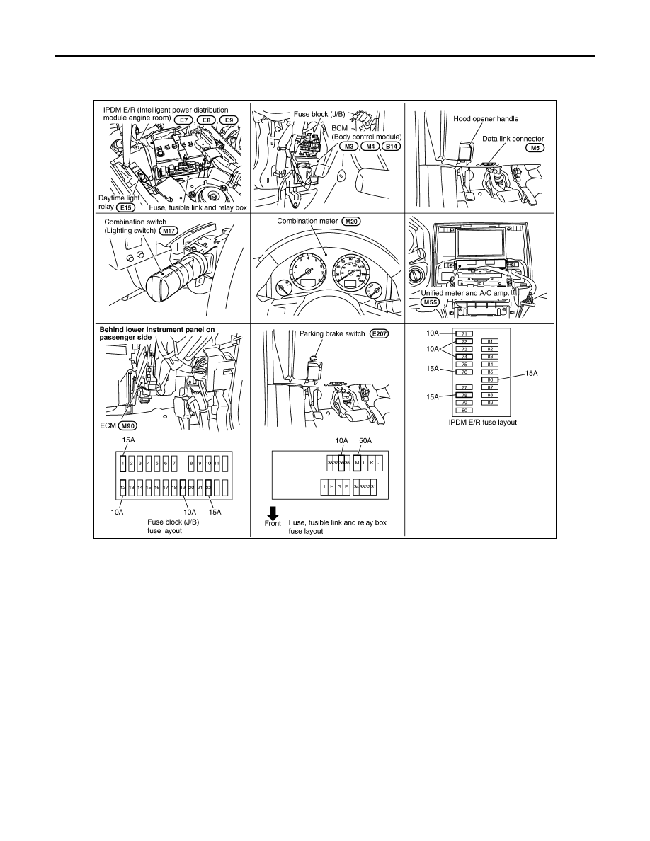
Component Parts and Harness Connector Location
INFOID:0000000001328291
System Description
INFOID:0000000001328292
Daytime light system turns ON daytime light lamps while driving. Daytime light lamps are not turned ON if
engine is activated with parking brake ON. Release parking brake to turn ON daytime light lamps. The lamps
turn OFF when the lighting switch is in the 2ND position or AUTO position (headlamp is ON) and when the
lighting switch is in the PASSING position (daytime light lamps are not turned OFF only by parking brake
itself).
The parking brake signal and engine run or stop signal are sent to BCM (body control module) by CAN com-
munication line, and control daytime light system.
OUTLINE
Power is supplied at all times
• through 10A fuse [No. 19, located in fuse block (J/B)]
• to combination meter terminal 8,
• through 15A fuse [No. 22, located in fuse block (J/B)]
• to BCM terminal 42,
• through 50A fusible link (letter M, located in fuse, fusible link and relay box)
• to BCM terminal 55,
• through 10A fuse (No. 36, located in fuse, fusible link and relay box)
• to daytime light relay terminals 2 and 5.
When ignition switch is in ON or START position, power is supplied
PKIC9686E
DAYTIME LIGHT SYSTEM
LT-33
< SERVICE INFORMATION >
C
D
E
F
G
H
I
J
L
M
A
B
LT
N
O
P
• through 10A fuse [No. 12, located in fuse block (J/B)]
• to combination meter terminal 7,
• through 15A fuse [No. 1, located in fuse block (J/B)]
• to BCM terminal 38.
Ground is supplied
• to combination meter terminals 5, 6 and 15
• through grounds M35, M45 and M85,
• to BCM terminals 49 and 52
• through grounds M35, M45 and M85.
DAYTIME LIGHT OPERATION
Once the parking brake is turned OFF after ignition switch ON, if the lighting switch is turned OFF while engine
running, the BCM sends daytime light request signal (ON) through CAN communication.
When receiving daytime light request signal (ON), combination meter turns ON daytime light relay. And power
is supplied
• through daytime light relay terminal 1
• to combination meter terminal 10,
• through daytime light relay terminal 3
• to parking lamp RH and LH terminals 1.
Ground is supplied
• to combination meter terminals 5, 6 and 15
• through grounds M35, M45 and M85,
• to parking lamp RH and LH terminals 3
• through grounds E21, E50 and E51.
With power and grounds supplied, the daytime light lamps illuminate.
COMBINATION SWITCH READING FUNCTION
AUTO LIGHT OPERATION
.
CAN Communication System Description
INFOID:0000000001328293
CAN (Controller Area Network) is a serial communication line for real time application. It is an on-vehicle mul-
tiplex communication line with high data communication speed and excellent error detection ability. Many elec-
tronic control units are equipped onto a vehicle, and each control unit shares information and links with other
control units during operation (not independent). In CAN communication, control units are connected with 2
communication lines (CAN-H line, CAN-L line) allowing a high rate of information transmission with less wiring.
Each control unit transmits/receives data but selectively reads required data only.
CAN Communication Unit
INFOID:0000000001328294
LT-34
< SERVICE INFORMATION >
DAYTIME LIGHT SYSTEM
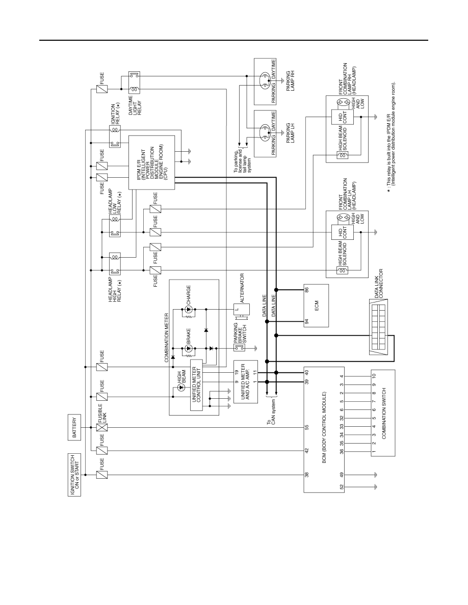
Schematic
INFOID:0000000001328295
TKWM4293E
Нет комментариевНе стесняйтесь поделиться с нами вашим ценным мнением.
Текст