Infiniti FX35 / FX45. Manual — part 847

IPDM E/R (INTELLIGENT POWER DISTRIBUTION MODULE ENGINE ROOM)
PG-21
< SERVICE INFORMATION >
C
D
E
F
G
H
I
J
L
M
A
B
PG
N
O
P
NOTE:
Turns ON-OFF the solenoid to switch Hi/Lo. In this case, the bulb does not illuminate.
Concept of Auto Active Test
• IPDM E/R actuates auto active test mode when it receives door switch signal from BCM via CAN communi-
cation line. Therefore, when auto active test mode is activated successfully, CAN communication between
IPDM E/R and BCM is normal.
• If any of systems controlled by IPDM E/R cannot be operated, possible cause can be easily diagnosed using
auto active test.
Diagnosis chart in auto active test mode
Symptom
Inspection contents
Possible cause
Any of front wipers, tail
and parking lamps, front
fog lamps, and head
lamps (Hi, Lo) do not op-
erate.
Perform auto active
test. Does system in
question operate?
YES
• BCM signal input system malfunction
NO
• Lamp/wiper motor malfunction
• Lamp/wiper motor ground circuit malfunction
• Harness/connector malfunction between IPDM E/R and system in question
• IPDM E/R (integrated relay) malfunction
Rear window defogger
does not operate.
Perform auto active
test. Does rear win-
dow defogger oper-
ate?
YES
• BCM signal input circuit malfunction
NO
• Rear window defogger relay malfunction
• Harness/connector malfunction between IPDM E/R and rear window de-
fogger relay.
• Open circuit of rear window defogger
• IPDM E/R malfunction
A/C compressor does
not operate.
Perform auto active
test. Does magnetic
clutch operate?
YES
• BCM signal input circuit malfunction
• CAN communication signal between BCM and ECM.
• CAN communication signal between ECM and IPDM E/R
NO
• Magnetic clutch malfunction
• Harness/connector malfunction between IPDM E/R and magnetic clutch
• IPDM E/R (integrated relay) malfunction
Cooling fan does not op-
erate.
Perform auto active
test. Does cooling
fan operate?
YES
• ECM signal input circuit
• CAN communication signal between ECM and IPDM E/R
NO
• Cooling fan motor malfunction
• Harness/connector malfunction between IPDM E/R and cooling fan motor
• IPDM E/R (integrated relay) malfunction
Oil pressure warning
lamp does not operate.
Perform auto active
test. Does oil pres-
sure warning lamp
blink?
YES
• Harness/connector malfunction between IPDM E/R and oil pressure switch
• Oil pressure switch malfunction
• IPDM E/R malfunction
NO
• CAN communication signal between BCM and unified meter and A/C amp.
• Combination meter

PG-22
< SERVICE INFORMATION >
IPDM E/R (INTELLIGENT POWER DISTRIBUTION MODULE ENGINE ROOM)
Schematic
INFOID:0000000001328876
TKWM4469E
IPDM E/R (INTELLIGENT POWER DISTRIBUTION MODULE ENGINE ROOM)
PG-23
< SERVICE INFORMATION >
C
D
E
F
G
H
I
J
L
M
A
B
PG
N
O
P
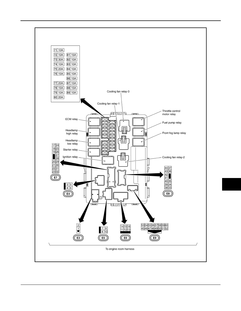
IPDM E/R Terminal Arrangement
INFOID:0000000001328877
IPDM E/R Power/Ground Circuit Inspection
INFOID:0000000001370717
1.
CHECK FUSE AND FUSIBLE LINK
Make sure the following fusible links or IPDM E/R fuses are not blown.
CKIM0237E
PG-24
< SERVICE INFORMATION >
IPDM E/R (INTELLIGENT POWER DISTRIBUTION MODULE ENGINE ROOM)
OK or NG
OK
>> GO TO 2.
NG
>> If fuse or fusible link blown, be sure to eliminate cause of malfunction before installing new one.
2.
CHECK POWER SUPPLY CIRCUIT
1.
Turn ignition switch OFF.
2.
Disconnect IPDM E/R harness connector.
3.
Check voltage between IPDM E/R harness connector and
ground.
OK or NG
OK
>> GO TO 3.
NG
>> Repair harness or connector.
3.
CHECK GROUND CIRCUIT
1.
Disconnect IPDM E/R harness connectors.
2.
Check continuity between IPDM E/R harness connectors and
ground.
OK or NG
OK
>> INSPECTION END
NG
>> Repair harness or connector.
U1000 CAN COMM CIRCUIT
INFOID:0000000001366489
1.
PERFORM SELF DIAGNOSTIC
1.
Turn ignition switch ON and wait for 2 seconds or more.
2.
Check “Self Diagnostic Result” of IPDM E/R.
Is “CAN COMM CIRCUIT” displayed?
YES
>> Refer to
LAN-43, "CAN System Specification Chart"
NO
>> Refer to
GI-25, "How to Perform Efficient Diagnosis for an Electrical Incident"
Removal and Installation of IPDM E/R
INFOID:0000000001328880
REMOVAL
1.
Remove battery. Refer to
SC-6, "Removal and Installation"
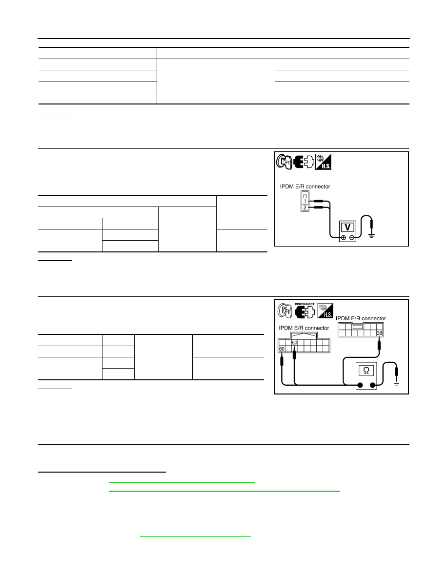
Terminal No.
Power source
Fuse and fusible link No.
1
Battery power
E
2
C
—
71
78
Terminals
Voltage (Ap-
prox.)
(+)
(-)
IPDM E/R connector
Terminal
Ground
E3
1
Battery voltage
2
PKIB6562E
IPDM E/R connector
Terminal
Ground
Continuity
E8
38
E9
50
Yes
60
SKIA6184E
Нет комментариевНе стесняйтесь поделиться с нами вашим ценным мнением.
Текст