Infiniti FX35 / FX45. Manual — part 846

IPDM E/R (INTELLIGENT POWER DISTRIBUTION MODULE ENGINE ROOM)
PG-17
< SERVICE INFORMATION >
C
D
E
F
G
H
I
J
L
M
A
B
PG
N
O
P
IPDM E/R (INTELLIGENT POWER DISTRIBUTION MODULE ENGINE
ROOM)
System Description
INFOID:0000000001328870
• IPDM E/R (Intelligent Power Distribution Module Engine Room) integrates the relay box and fuse block
which were originally placed in engine compartment. It controls integrated relay via IPDM E/R control circuit.
• IPDM E/R-integrated control circuit performs ON-OFF operation of relay, CAN communication control, oil
pressure switch signal, and hood switch signal reception, etc.
• It controls operation of each electrical part via ECM, BCM and CAN communication lines.
CAUTION:
None of the IPDM E/R-integrated relays can be removed.
SYSTEMS CONTROLLED BY IPDM E/R
IPDM E/R receives a request signal from each control unit with CAN communication. It controls each system.
CAN COMMUNICATION LINE CONTROL
With CAN communication, by connecting each control unit using two communication lines (CAN-L line, CAN-H
line), it is possible to transmit maximum amount of information with minimum wiring. Each control unit can
transmit and receive data, and reads necessary information only.
Fail- Safe Control
• When CAN communication with other control units is impossible, IPDM E/R performs fail-safe control. After
CAN communication recovers normally, it also returns to normal control.
• Operation of control parts by IPDM E/R during fail-safe mode is as follows:
IPDM E/R STATUS CONTROL
In order to save power, IPDM E/R switches status by itself based on each operating condition.
1.
CAN communication status
• CAN communication is normally performed with other control units.
• Individual unit control by IPDM E/R is normally performed.
• When sleep request signal is received from BCM, mode is switched to sleep waiting status.
2.
Sleep waiting status
• Process to stop CAN communication is activated.
Control system
Transmit control unit
Control part
Lamp control
BCM
• Headlamps (HI, LO)
• Front fog lamps
• Parking, license plate, side marker and tail lamps
Wiper control
BCM
Front wipers
Rear window defogger control
BCM
Rear window defogger
A/C compressor control
ECM
A/C compressor (magnet clutch)
Cooling fan control
ECM
Cooling fan
Horn control
BCM
Horn
Controlled system
Fail-safe mode
Headlamp
• With the ignition switch ON, the headlamp (low) is ON.
• With the ignition switch OFF, the headlamp (low) is OFF.
Parking, license plate side marker, and
tail lamps
• With the ignition switch ON, the parking, license plate, side marker and tail lamps is ON.
• With the ignition switch OFF, the parking, license plate, side marker and tail lamps is OFF.
Cooling fan
• With the ignition switch ON, the cooling fan HI operates.
• With the ignition switch OFF, the cooling fan stops.
Front wiper
Until the ignition switch is turned OFF, the front wiper LO and HI remains in the same status
it was in just before fail-safe control was initiated.
Rear window defogger
Rear window defogger relay OFF
A/C compressor
A/C compressor OFF
Front fog lamps
Front fog lamp relay OFF

PG-18
< SERVICE INFORMATION >
IPDM E/R (INTELLIGENT POWER DISTRIBUTION MODULE ENGINE ROOM)
• All systems controlled by IPDM E/R are stopped. When 3 seconds have elapsed after CAN communica-
tion with other control units is stopped, mode switches to sleep status.
3.
Sleep status
• IPDM E/R operates in low power mode.
• CAN communication is stopped.
• When a change in CAN communication line is detected, mode switches to CAN communication status.
• When a change hood switch or ignition switch signal is detected, mode switches to CAN communication
status.
CAN Communication System Description
INFOID:0000000001328871
CAN (Controller Area Network) is a serial communication line for real time application. It is an on-vehicle mul-
tiplex communication line with high data communication speed and excellent error detection ability. Modern
vehicles are equipped with many electronic control units and each control unit shares information and links
with other control units during operation (not independent). In CAN communication, control units are con-
nected with 2 communication lines (CAN-H line, CAN-L line) allowing a high rate of information transmission
with less wiring. Each control unit transmits/receives data but selectively reads required data only.
CAN Communication Unit
INFOID:0000000001328872
LAN-43, "CAN System Specification Chart"
Function of Detecting Ignition Relay Malfunction
INFOID:0000000001328873
• When contact point of integrated ignition relay is stuck and cannot be turned OFF, IPDM E/R turns ON park-
ing, license plate, side marker and tail lamps for 10 minutes to indicate ignition relay malfunction.
• When a state of ignition relay having built-in does not agree with a state of ignition switch signal input by a
CAN communication from BCM, IPDM E/R lets tail lamp relay operate.
NOTE:
When the ignition switch is turned ON, the tail lamps are OFF.
CONSULT-III Function (IPDM E/R)
INFOID:0000000001328874
CONSULT-III can display each diagnostic item using the diagnostic test mode shown following.
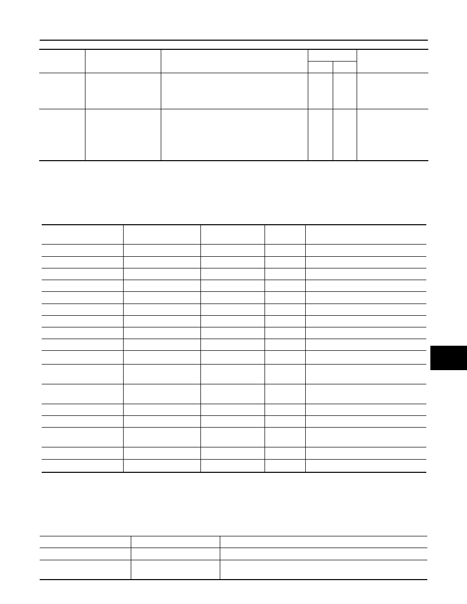
Self Diagnostic Result
Display Item List
Ignition switch signal
Ignition relay status
Tail lamp relay
ON
ON
—
OFF
OFF
—
ON
OFF
—
OFF
ON
ON (10 minutes)
Inspection Item, Diagnosis Mode
Description
Self Diagnostic Result
The IPDM E/R performs diagnosis of the CAN communication and self-diagnosis.
Data Monitor
The input/output data of the IPDM E/R is displayed in real time.
CAN Diag Support Monitor
The result of transmit/receive diagnosis of CAN communication can be read.
Active test
The IPDM E/R sends a drive signal to electronic components to check their operation.
IPDM E/R (INTELLIGENT POWER DISTRIBUTION MODULE ENGINE ROOM)
PG-19
< SERVICE INFORMATION >
C
D
E
F
G
H
I
J
L
M
A
B
PG
N
O
P
NOTE:
The details for display of the period are as follows:
• CRNT: Error currently detected with IPDM E/R.
• PAST: Error detected in the past and memorized with IPDM E/R.
DATA MONITOR
NOTE:
• Perform monitoring of IPDM E/R data with the ignition switch ON. When the ignition switch is at ACC, the display may not be correct.
• *1: The vehicle without the Intelligent Key system displays only ON without change.
• *2:The cornering lamp item is displayed, but it cannot be monitored.
ACTIVE TEST
DTC
Display Items
Malfunction detecting condition
TIME
Possible causes
CRNT
PAST
—
NO DTC IS DETECT-
ED.FURTHER TEST-
ING MAY BE
REQUIRED.
—
—
—
—
U1000
CAN COMM CIRCUIT
• If CAN communication reception/transmission
data has a malfunction, or if any of the control
units malfunction, data reception/transmission
cannot be confirmed.
• When the data in CAN communication is not re-
ceived before the specified time
×
×
Any of or several items
below have errors.
• TRANSMIT DIAG
• ECM
• BCM/SEC
Item name
CONSULT-III screen dis-
play
Display or unit
MAIN SIG-
NALS
Description
Motor fan request
MOTOR FAN REQ
1/2/3/4
×
Signal status input from ECM
Compressor request
AC COMP REQ
On/Off
×
Signal status input from ECM
Tail & clear request
TAIL&CLR REQ
On/Off
×
Signal status input from BCM
H/L LO request
HL LO REQ
On/Off
×
Signal status input from BCM
H/L HI request
HL HI REQ
On/Off
×
Signal status input from BCM
FR fog request
FR FOG REQ
On/Off
×
Signal status input from BCM
FR wiper request
FR WIP REQ
Stop/1LOW/Lo/Hi
×
Signal status input from BCM
Wiper auto stop
WIP AUTO STOP
ACT P/STOP P
×
Output status of IPDM E/R
Wiper protection
WIP PROT
Off/BLOCK
×
Control status of IPDM E/R
Starter request
ST RLY REQ
*1
On/Off
Status of input signal
Ignition relay status
IGN RLY
On/Off
×
Ignition relay status monitored with
IPDM E/R
Rear window defogger re-
quest
RR DEF REQ
On/Off
×
Signal status input from BCM
Oil pressure switch
OIL P SW
Open/Close
Signal status input in IPDM E/R
Hood switch
HOOD SW
On/Off
Input signal status
Theft warning horn re-
quest
THFT HRN REQ
On/Off
Signal status input from BCM
Horn chirp
HORN CHIRP
On/Off
Output status of IPDM E/R
Cornering lamp request
CRNRNG LMP REQ
*2
Off
Signal status input from BCM
Test item
CONSULT-III screen display
Description
Tail lamp operation
TAIL LAMP
With a certain On-Off operation, the tail lamp relay can be operated.
Rear window defogger opera-
tion
REAR DEFOGGER
With a certain On-Off operation, the rear window defogger relay can be
operated.
PG-20
< SERVICE INFORMATION >
IPDM E/R (INTELLIGENT POWER DISTRIBUTION MODULE ENGINE ROOM)
NOTE:
This item is displayed, but cannot be tested.
Auto Active Test
INFOID:0000000001328875
DESCRIPTION
In auto active test mode, operation inspection can be performed when IPDM E/R sends a drive signal to the
following systems:
• Rear window defogger
• Front wipers
• Parking, license plate, side marker and tail lamps
• Front fog lamps
• Headlamps (Hi, Lo)
• A/C compressor (magnetic clutch)
• Cooling fan
OPERATION PROCEDURE
1.
Close hood and front door (passenger side), and then lift wiper arms away from windshield (to prevent
glass damage by wiper operation).
NOTE:
When auto active test is performed with hood opened, sprinkle water on windshield beforehand.
2.
Turn ignition switch OFF.
3.
Turn ignition switch ON, and within 20 seconds, press drivers door switch 10 times (close other doors).
Then turn ignition switch OFF.
4.
Turn ignition switch ON within 10 seconds after ignition switch OFF.
5.
When auto active test mode is actuated, horn chirps once oil pressure warning lamp starts blinking.
6.
After a series of operations is repeated three times, auto active test is completed.
NOTE:
When auto active test mode has to be cancelled halfway, turn ignition switch OFF.
CAUTION:
when the auto active test cannot be performed.
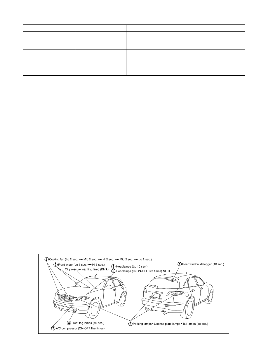
INSPECTION IN AUTO ACTIVE TEST MODE
When auto active test mode is actuated, the following eight steps are repeated three times.
Front wiper (HI, LO) operation
FRONT WIPER
With a certain operation (Off, Hi, Lo), the front wiper relay (Lo, Hi) can
be operated.
Cooling fan operation
MOTOR FAN
With a certain operation (1, 2, 3, 4), the cooling fan can be operated.
Lamp (HI, LO, FOG) opera-
tion
LAMPS
With a certain operation (Off, Hi, Lo, Fog), the lamp relay (Lo, Hi, Fog)
can be operated.
Cornering lamp operation
CORNERING LAMP
NOTE
—
Horn operation
HORN
With a certain On-Off operation, the horn relay can be operated.
Test item
CONSULT-III screen display
Description
PKIB6583E
Нет комментариевНе стесняйтесь поделиться с нами вашим ценным мнением.
Текст