Infiniti FX35 / FX45. Manual — part 248
BRAKE FLUID
BR-9
< SERVICE INFORMATION >
C
D
E
G
H
I
J
K
L
M
A
B
BR
N
O
P
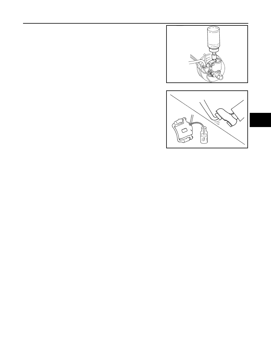
• Carefully monitor brake fluid level in reservoir tank
during bleeding operation.
• Refill with new brake fluid “DOT 3”. Make sure it is at least half
way at all times while bleeding air out of system.
• Place a container under master cylinder not to spill brake
fluid.
• Turn ignition switch OFF and disconnect ABS actuator and
electric unit (control unit) or battery negative terminal.
• Bleed air in the following order. Right rear brake
→
Left front
brake
→
Left rear brake
→
Right front brake
1.
Connect a transparent vinyl tube to bleed valve.
2.
Fully depress brake pedal several times.
3.
With brake pedal depressed, open bleed valve to release air.
4.
Close bleed valve.
5.
Release brake pedal slowly.
6.
Repeat steps 2, through 5, until clear brake fluid comes out of
bleed valve.
SBR995
SBR419C
BR-10
< SERVICE INFORMATION >
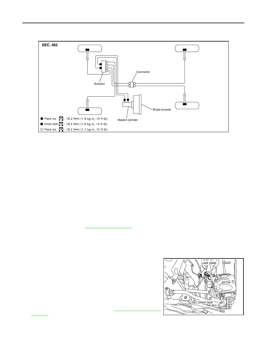
BRAKE TUBE AND HOSE
BRAKE TUBE AND HOSE
Hydraulic Circuit
INFOID:0000000001327613
CAUTION:
• All brake hoses and tubes must be free from excessive bending, twisting and pulling.
• Make sure there is no interference with other parts when turning steering both clockwise and coun-
terclockwise.
• The brake tubes and hoses is an important safety part. If a brake fluid leak is detected, always disas-
semble the parts. Replace applicable part with a new one, if necessary.
• Be careful not to splash brake fluid on painted areas; it way cause paint damage. If brake fluid is
splashed on painted surfaces of body, immediately wipe it off and them wash it away with water
immediately.
• Do not bend or twist brake hose sharply, or strongly pull it.
• When removing components, cover brake line connections so that no dirt, no dust, or other foreign
matter gets in.
• Refill with new brake fluid “ DOT 3 ”.
• Do not reuse drained brake fluid.
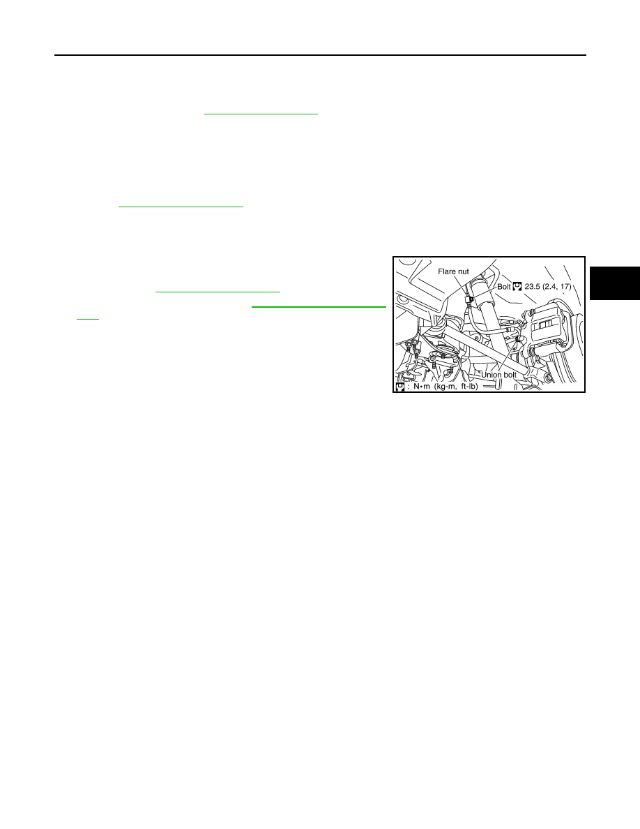
Removal and Installation of Front Brake Tube and Brake Hose
INFOID:0000000001327614
REMOVAL
1.
Drain brake fluid. Refer to
.
2.
Using a flare nut wrench, remove brake tube from brake hose.
3.
Remove union bolt and remove brake hose from caliper assembly.
4.
Remove lock plate and remove brake hose from vehicle.
INSTALLATION
1.
Position brake hose by aligning with the protrusion on caliper
assembly, and them tighten union bolt to the specified torque.
CAUTION:
Do not reuse copper washer.
2.
Install brake hose to brake tube. Temporarily tighten flare nut by
hand as much as possible. Secure them it to bracket with lock
plate.
3.
Using a flare nut torque wrench, tighten flare nut to the specified
torque.
4.
Refill brake fluid and bleed air. Refer to
PFIA0818E
SFIA1204E
BRAKE TUBE AND HOSE
BR-11
< SERVICE INFORMATION >
C
D
E
G
H
I
J
K
L
M
A
B
BR
N
O
P
Removal and Installation of Rear Brake Piping and Brake Hose
INFOID:0000000001327615
REMOVAL
1.
Drain brake fluid. Refer to
.
2.
Using a flare nut wrench, remove brake tube from brake hose.
3.
Remove union bolt, and then remove brake hose from caliper assembly.
4.
Remove lock nut plate and remove brake hose from vehicle.
INSTALLATION
1.
Install brake hose to caliper assembly positioning hole and then tighten union bolt to the specified torque.
Refer to
CAUTION:
Do not reuse copper washer.
2.
Connect brake hose to brake tube. Temporarily tighten flare nut by hand as much as possible.
3.
Tighten brake hose mounting bolt to the specified torque.
4.
Using a flare nut torque wrench, tighten flare nut to the specified
torque. Refer to
.
5.
After installation, bleed air. Refer to
Inspection After Installation
INFOID:0000000001327616
CAUTION:
If a leak is detected at the connections, retighten it or replace damaged part if necessary.
1.
Check brake lines (tubes and hoses), and connections for fluid leakage, damage, twist, deformation, con-
tact with other parts, and loose connections.
2.
While depressing brake pedal under a force of 785 N (80 kg, 177 lb) with engine running for approximately
5 seconds, check for fluid leak from each part.
SFIA1942E
BR-12
< SERVICE INFORMATION >
BRAKE MASTER CYLINDER
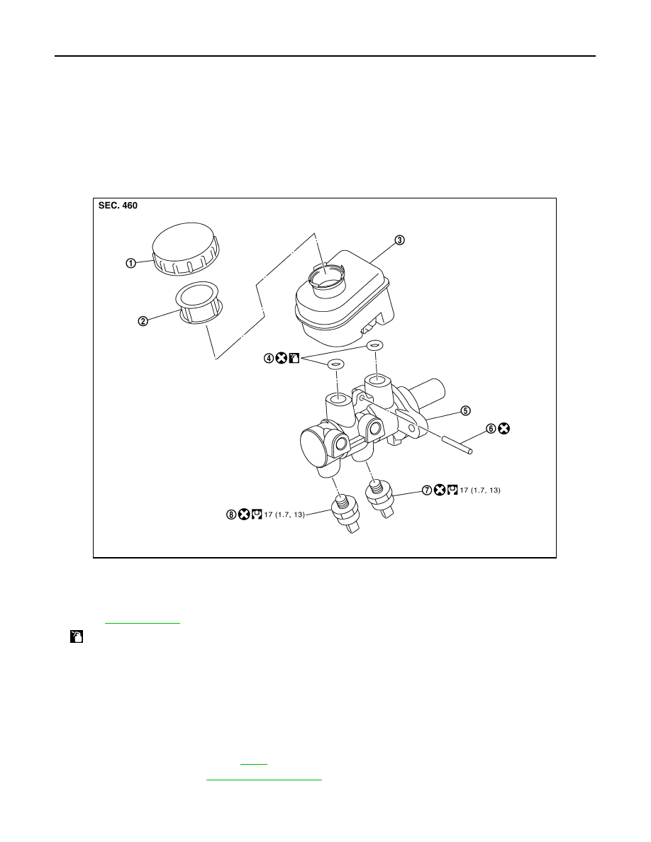
BRAKE MASTER CYLINDER
On-Board Inspection
INFOID:0000000001327617
LEAK INSPECTION
• Check for leaking in a master cylinder installation surface, a reservoir tank installation surface, and brake
tube connections.
Component
INFOID:0000000001327618
Removal and Installation
INFOID:0000000001327619
CAUTION:
Be careful not to splash brake fluid on painted areas; it way cause paint damage. If brake fluid is
splashed on painted surfaces of body, immediately wipe it off and them wash it away with water imme-
diately.
REMOVAL
1.
Remove cowl top cover. Refer to
2.
Drain brake fluid. Refer to
.
3.
Remove harness connectors for fluid level sensor and pressure sensor.
4.
Using a flare nut wrench, remove brake tube from master cylinder assembly.
1.
Reservoir cap
2.
Strainer
3.
Reservoir tank
4.
Grommet
5.
Cylinder body
6.
Pin
7.
Pressure sensor
8.
Pressure sensor (Only ICC models)
Refer to
and the followings for the symbols in the figure.
: Apply brake fluid.
PFIA0815E
Нет комментариевНе стесняйтесь поделиться с нами вашим ценным мнением.
Текст