Infiniti FX35 / FX45. Manual — part 654
CYLINDER BLOCK
EM-133
< SERVICE INFORMATION >
[VQ35DE]
C
D
E
F
G
H
I
J
K
L
M
A
EM
N
P
O
d.
Then tighten all connecting rod bolts 90 degrees clockwise
(Angle tightening).
CAUTION:
Always use the angle wrench [SST: KV10112100 (BT8653-
A)]. Avoid tightening based on visual check alone.
• After tightening connecting rod bolts, make sure that crank-
shaft rotates smoothly.
• Check the connecting rod side clearance. Refer to
"Inspection After Disassembly"
.
15. Install baffle plate to main bearing beam (2WD models).
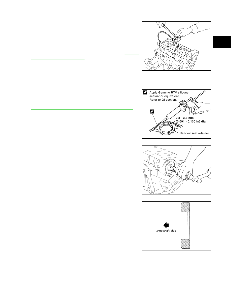
16. Install new rear oil seal retainer to cylinder block.
• Apply new engine oil to both oil seal lip and dust seal lip.
• Apply a continuous bead of liquid gasket with the tube presser
(commercial service tool) to rear oil seal retainer as shown in
the figure.
Use Genuine RTV Silicone Sealant or equivalent. Refer to
GI-44, "Recommended Chemical Product and Sealant"
.
CAUTION:
• Replace with a new parts.
• Attaching should be done within 5 minutes after coating.
• Make sure the garter spring is in position and seal lips not
inverted.
NOTE:
Regard both rear oil seal and retainer as an assembly.
17. Install pilot converter.
• With a drift [outer diameter: approx. 33 mm (1.30 in)], press-fit
as far as it will go.
• Press-fit pilot converter with its chamfer facing crankshaft as
shown in the figure.
SEM953E
PBIC2661E
PBIC0899E
SEM537E
EM-134
< SERVICE INFORMATION >
[VQ35DE]
CYLINDER BLOCK
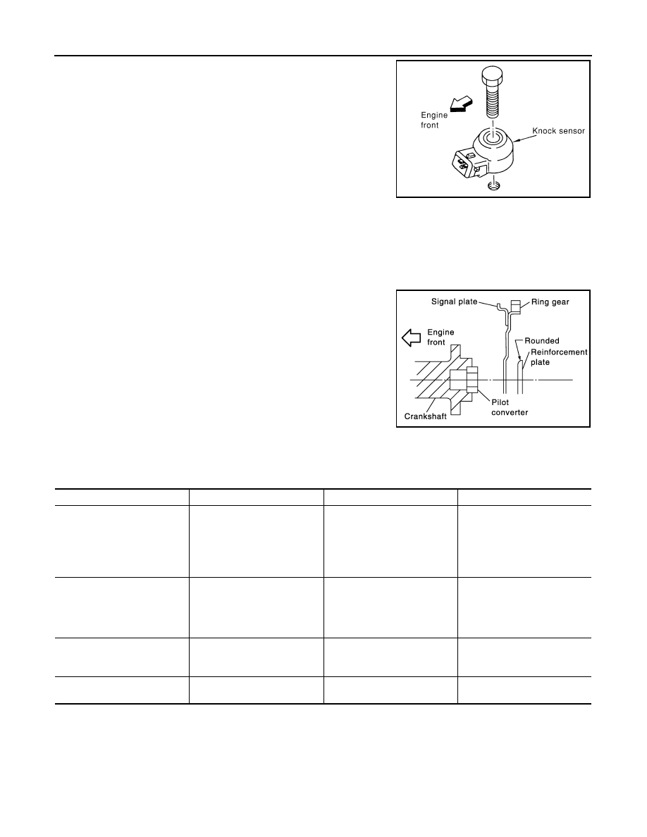
18. Install knock sensor.
• Install knock sensor so that connector faces front of the
engine.
• After installing knock sensor, connect harness connector, and
lay it out to rear of the engine.
CAUTION:
• Do not tighten mounting bolts while holding connector.
• If any impact by dropping is applied to knock sensor,
replace it with new one.
NOTE:
• Make sure that there is no foreign material on the cylinder
block mating surface and the back surface of knock sensor.
• Make sure that knock sensor does not interfere with other parts.
19. Note the following, assemble in the reverse order of disassembly after this step.
Drive plate
• When installing drive plate to crankshaft, be sure to correctly align crankshaft side guide pin and drive
plate side guide pin hole.
- If these are not aligned correctly, engine runs roughly and “MIL” turns on.
• Install drive plate and reinforcement plate as shown in the fig-
ure.
• Holding ring gear with the ring gear stopper [SST:
KV10117700 (J44716)].
• Tighten the mounting bolts crosswise over several times.
CAUTION:
Make sure that dowel pin is installed at the rear end of
crankshaft.
How to Select Piston and Bearing
INFOID:0000000001325748
DESCRIPTION
*: For the service parts, the grade for fitting cannot be selected between piston pin and connecting rod. (Only “0” grade is available.) The
information at the shipment from the plant is described as a reference.
• The identification grade stamped on each part is the grade for the dimension measured in new condition.
This grade cannot apply to reused parts.
• For reused or repaired parts, measure the dimension accurately. Determine the grade by comparing the
measurement with the values of each selection table.
• For details of the measurement method of each part, the reuse standards and the selection method of the
selective fitting parts, refer to the text.
PBIC0810E
PBIC0910E
Selection points
Selection parts
Selection items
Selection methods
Between cylinder block and
crankshaft
Main bearing
Main bearing grade
(bearing thickness)
Determined by match of cylin-
der block bearing housing
grade (inner diameter of hous-
ing) and crankshaft journal
grade (outer diameter of jour-
nal)
Between crankshaft and con-
necting rod
Connecting rod bearing
Connecting rod bearing grade
(bearing thickness)
Combining service grades for
connecting rod big end diame-
ter and crankshaft pin outer di-
ameter determine connecting
rod bearing selection.
Between cylinder block and pis-
ton
Piston and piston pin assembly
(Piston is available together
with piston pin as assembly.)
Piston grade
(piston skirt diameter)
Piston grade = cylinder bore
grade (inner diameter of bore)
Between piston and connecting
rod*
—
—
—
CYLINDER BLOCK
EM-135
< SERVICE INFORMATION >
[VQ35DE]
C
D
E
F
G
H
I
J
K
L
M
A
EM
N
P
O
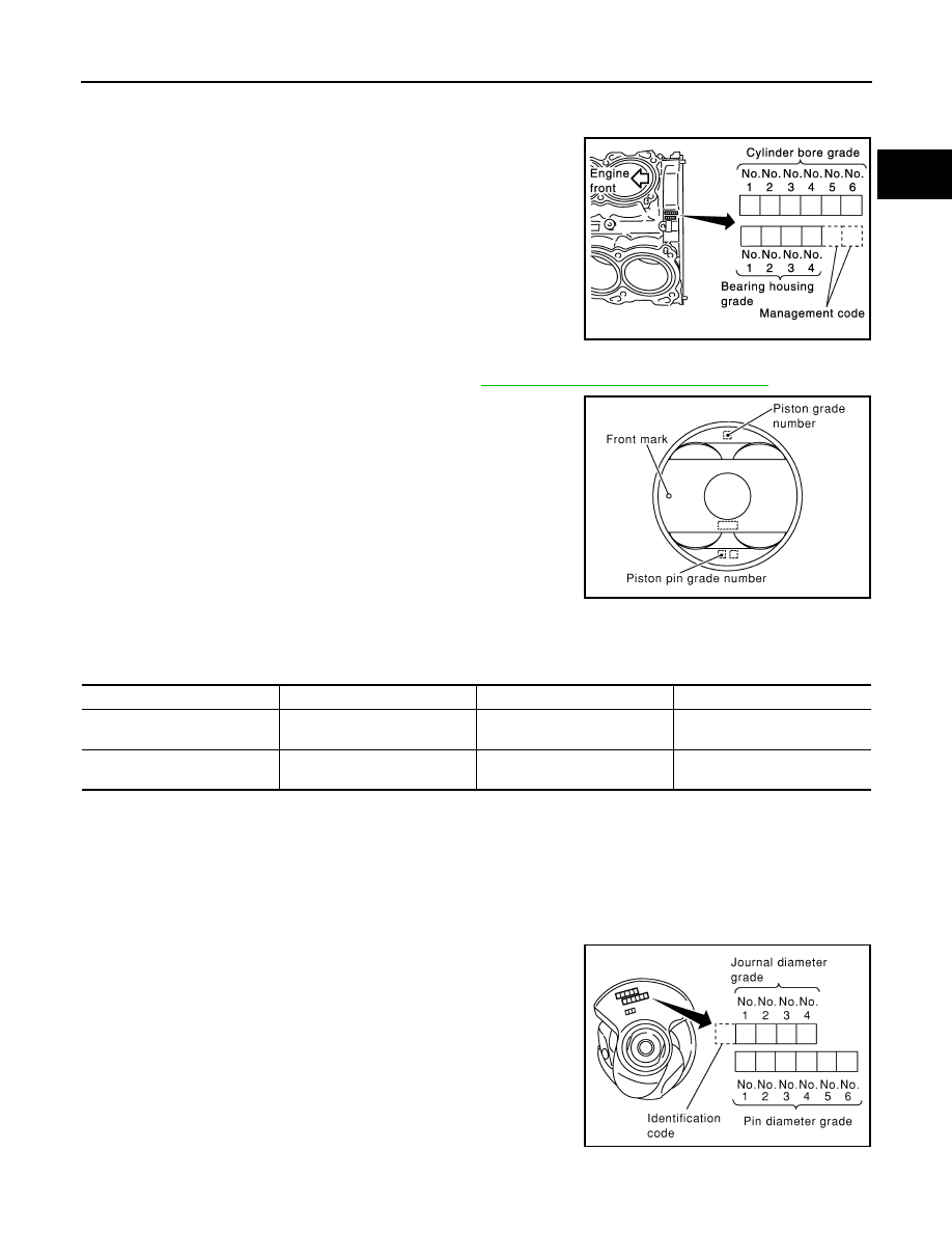
HOW TO SELECT PISTON
When New Cylinder Block is Used
Check the cylinder bore grade (“1”, “2” or “3”) on rear side of cylinder
block, and select piston of the same grade.
NOTE:
Piston is available with piston pin as a set for the service part. (Only
“0” grade piston pin is available.)
When Cylinder Block is Reused
1.
Measure the cylinder bore inner diameter. Refer to
EM-138, "Inspection After Disassembly"
.
2.
Determine the bore grade by comparing the measurement with
the values under the cylinder bore inner diameter of the “Piston
Selection Table”.
3.
Select piston of the same grade.
Piston Selection Table
Unit: mm (in)
NOTE:
• Piston is available together with piston pin as assembly.
• Piston pin (piston pin hole) grade is provided only for the parts installed at the plant. For service parts, no pis-
ton pin grades can be selected. (Only “0” grade is available.)
• No second grade mark is available on piston.
HOW TO SELECT CONNECTING ROD BEARING
When New Connecting Rod and Crankshaft are Used
Check pin diameter grade (“0”, “1” or “2”) on front of crankshaft, and
select connecting rod bearing of the same grade.
NOTE:
There is no grading for connecting rod big end diameter.
When Crankshaft and Connecting Rod are Reused
SEM756G
PBIC0812E
Grade
1
2 (or no mark)
3
Cylinder bore inner diameter
95.500 - 95.510
(3.7598 - 3.7602)
95.510 - 95.520
(3.7602 - 3.7606)
95.520 - 95.530
(3.7606 - 3.7610)
Piston skirt diameter
95.480 - 95.490
(3.7590 - 3.7594)
95.490 - 95.500
(3.7594 - 3.7598)
95.500 - 95.510
(3.7598 - 3.7602)
SEM452G
EM-136
< SERVICE INFORMATION >
[VQ35DE]
CYLINDER BLOCK
1.
Measure the connecting rod big end diameter. Refer to
EM-138, "Inspection After Disassembly"
.
2.
Make sure that the connecting rod big end diameter is within the standard value.
3.
Measure the crankshaft pin journal diameter. Refer to
EM-138, "Inspection After Disassembly"
.
4.
Determine the grade of crankshaft pin diameter grade by corresponding to the measured dimension in
“Crankshaft pin journal diameter” column of “Connecting Rod Bearing Selection Table”.
5.
Select connecting rod bearing of the same grade.
Connecting Rod Bearing Selection Table
Unit: mm (in)
Unit: mm (in)
Undersize Bearings Usage Guide
• When the specified connecting rod bearing oil clearance is not obtained with standard size connecting rod
bearings, use undersize (US) bearings.
• When using undersize (US) bearing, measure the connecting rod bearing inner diameter with bearing
installed, and grind crankshaft pin so that the connecting rod bearing oil clearance satisfies the standard.
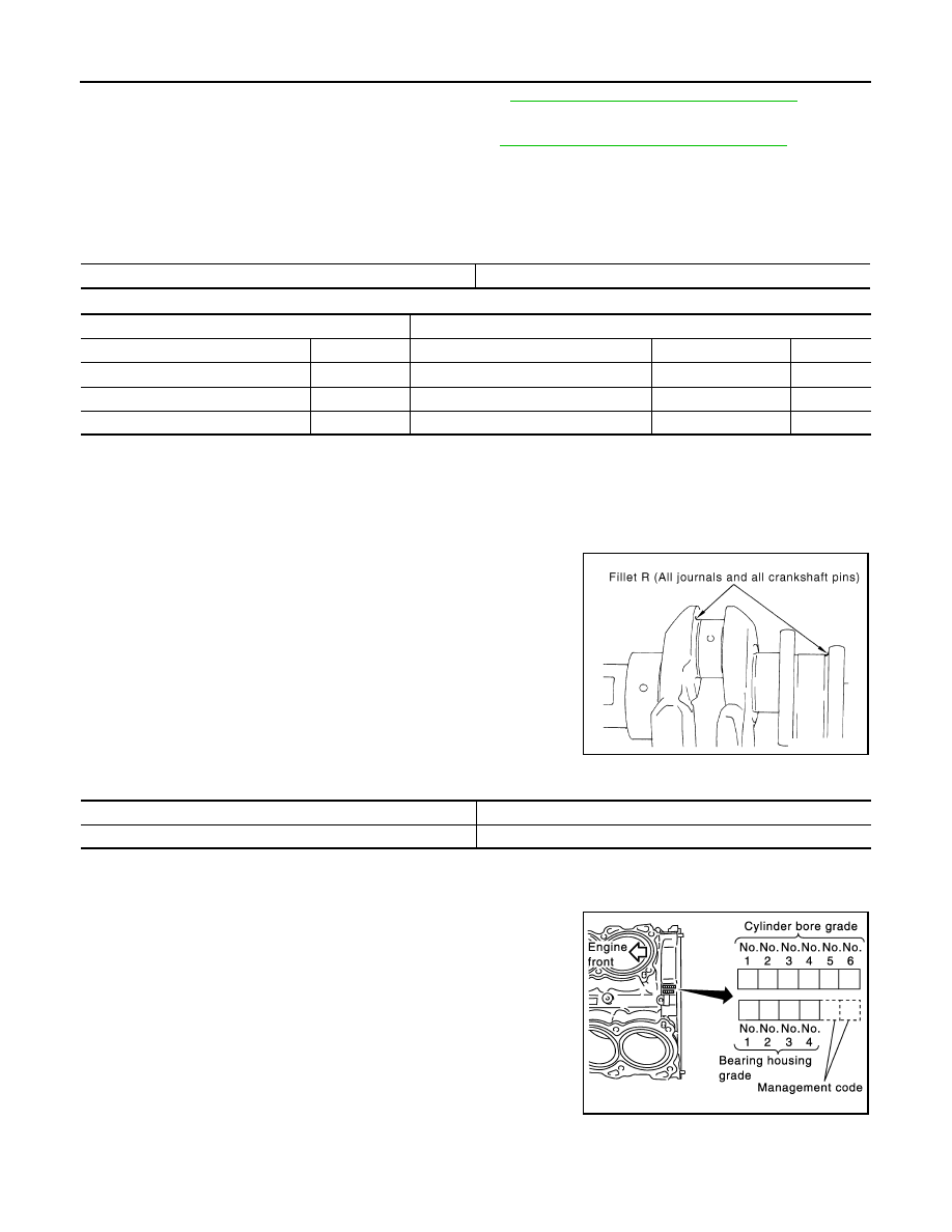
CAUTION:
In grinding crankshaft pin to use undersize bearings, keep the
fillet R [1.5 - 1.7 mm (0.059 - 0.067 in)].
Bearing undersize table
Unit: mm (in)
HOW TO SELECT MAIN BEARING
When New Cylinder Block and Crankshaft are Used
1.
“Main Bearing Selection Table” rows correspond to bearing
housing grade on rear left side of cylinder block.
Connecting rod big end diameter
55.000 - 55.013 (2.1654 - 2.1659)
Crankshaft
Connecting rod bearing
Crankshaft pin journal diameter
Grade (Mark)
Dimension (Bearing thickness range)
Bearing grade No.
Color
51.968 - 51.974 (2.0460 - 2.0462)
0
1.500 - 1.503 (0.0591 - 0.0592)
STD 0
Black
51.962 - 51.968 (2.0457 - 2.0460)
1
1.503 - 1.506 (0.0592 - 0.0593)
STD 1
Brown
51.956 - 51.962 (2.0455 - 2.0457)
2
1.506 - 1.509 (0.0593 - 0.0594)
STD 2
Green
PBIC1908E
Size
Thickness
US 0.25 (0.0098)
1.626 - 1.634 (0.0640 - 0.0643)
SEM756G
Нет комментариевНе стесняйтесь поделиться с нами вашим ценным мнением.
Текст