Infiniti FX35 / FX45. Manual — part 652
CYLINDER BLOCK
EM-125
< SERVICE INFORMATION >
[VQ35DE]
C
D
E
F
G
H
I
J
K
L
M
A
EM
N
P
O
6.
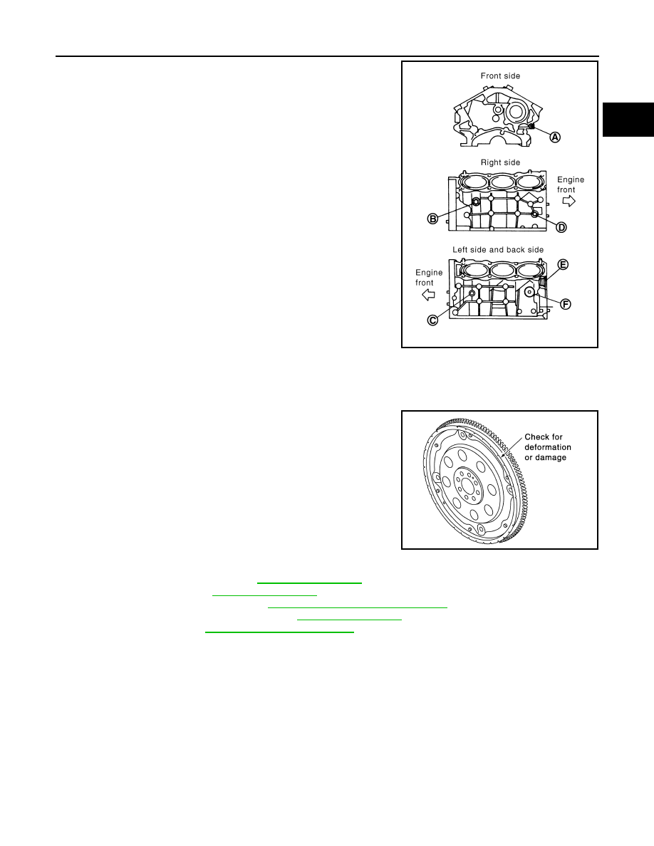
Drain engine coolant by removing water drain plugs from cylin-
der block both sides at “B” and “C” and cylinder block front side
at “A” as shown in the figure.
7.
Remove drive plate with power tool. Fix crankshaft with a ring gear stopper [SST: KV1011770 (J44716)],
and remove mounting bolts.
• Loosen mounting bolts in diagonal order.
CAUTION:
• Do not disassemble drive plate.
• Never place drive plate with signal plate facing down.
• When handling signal plate, take care not to damage or
scratch it.
• Handle signal plate in a manner that prevents it from
becoming magnetized.
8.
Remove the following parts:
• Intake manifold collector: Refer to
• Intake manifold: Refer to
.
• Oil pans (lower and upper): Refer to
EM-30, "Component (2WD Models)"
.
• Front and rear timing chain case: Refer to
.
9.
Remove knock sensor.
CAUTION:
Carefully handle sensor avoiding shocks.
PBIC2610E
SEM760G
EM-126
< SERVICE INFORMATION >
[VQ35DE]
CYLINDER BLOCK
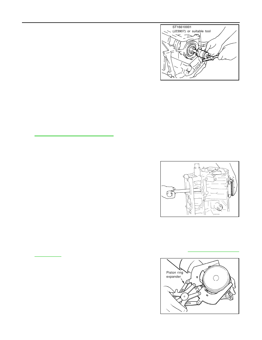
10. Remove pilot converter using the pilot bushing puller (SST) as
necessary.
11. Remove rear oil seal retainer.
• Remove by inserting a screwdriver between main bearing cap and rear oil seal retainer.
CAUTION:
If rear oil seal retainer is removed, replace it with new one.
NOTE:
Regard both rear oil seal and retainer as an assembly.
12. Remove baffle plate from main bearing beam (2WD models).
13. Remove piston and connecting rod assembly with the following procedure:
• Before removing piston and connecting rod assembly, check the connecting rod side clearance. Refer to
EM-138, "Inspection After Disassembly"
CAUTION:
Be careful not to drop connecting rod bearing, and to scratch the surface.
a.
Position crankshaft pin corresponding to connecting rod to be removed onto the bottom dead center.
b.
Remove connecting rod bearing cap.
c.
Using a hammer handle or similar tool, push piston and connect-
ing rod assembly out to the cylinder head side.
CAUTION:
Be careful not to damage the cylinder wall and crankshaft
pin, resulting from an interference of the connecting rod big
end.
14. Remove connecting rod bearings from connecting rod and connecting rod bearing cap.
CAUTION:
• Be careful not to drop connecting rod bearing, and to scratch the surface.
• Identify installation positions, and store them without mixing them up.
15. Remove piston rings form piston.
• Before removing piston rings, check the piston ring side clearance. Refer to
.
• Use a piston ring expander (commercial service tool).
CAUTION:
• When removing piston rings, be careful not to damage
piston.
• Be careful not to damage piston rings by expanding them
excessively.
16. Remove piston from connecting rod as follows:
SEM005G
EMQ0191D
PBIC0087E
CYLINDER BLOCK
EM-127
< SERVICE INFORMATION >
[VQ35DE]
C
D
E
F
G
H
I
J
K
L
M
A
EM
N
P
O
a.
Using a snap ring pliers, remove snap rings.
b.
Heat piston to 60 to 70
°
C (140 to 158
°
F) with an industrial use
drier or equivalent.
c.
Push out piston pin with stick of outer diameter approximately 20
mm (0.79 in).
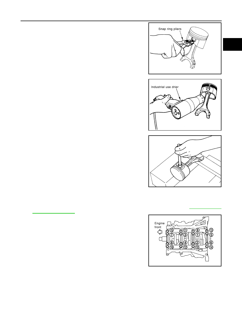
17. Remove main bearing cap bolts.
NOTE:
Use TORX socket (size E14).
• Before loosening main bearing cap bolts, measure the crankshaft end play. Refer to
.
• Loosen main bearing cap bolts in the reverse order shown in
the figure in several different steps.
PBIC1638E
PBIC1639E
PBIC0262E
PBIC1800E

EM-128
< SERVICE INFORMATION >
[VQ35DE]
CYLINDER BLOCK
18. Remove main bearing beam.
19. Remove main bearing caps.
CAUTION:
Be careful not to drop main bearing, and to scratch the sur-
face.
• Using main bearing cap bolts, remove main bearing cap while
shaking it back-and-forth.
20. Remove crankshaft.
21. Remove main bearings and thrust bearings from cylinder block and main bearing caps.
CAUTION:
• Be careful not to drop main bearing, and to scratch the surface.
• Identify installation positions, and store them without mixing them up.
22. Remove oil jet.
ASSEMBLY
1.
Fully air-blow engine coolant and engine oil passages in cylinder block, cylinder bore and crankcase to
remove any foreign material.
CAUTION:
Use a goggles to protect your eye.
2.
Install each plug to cylinder block as shown in the figure.
• Apply sealant to the thread of water drain plugs “A”, “B” and
“C”.
Use Genuine RTV Silicone Sealant or equivalent. Refer to
GI-44, "Recommended Chemical Product and Sealant"
• Apply sealant to the thread of plugs “D” and “E”.
Use Genuine High Strength Thread Locking Sealant or
equivalent. Refer to
• Apply sealant to the thread of plug “F”.
Use Anaerobic Liquid Gasket or equivalent. Refer to
44, "Recommended Chemical Product and Sealant"
NOTE:
For Canada, “F” in the figure is not plug but block heater. Refer
to
.
• Replace washers with new one.
PBIC0881E
EMQ0195D
PBIC2610E
Нет комментариевНе стесняйтесь поделиться с нами вашим ценным мнением.
Текст