Infiniti FX35 / FX45. Manual — part 774
TROUBLE DIAGNOSIS
LAN-73
< SERVICE INFORMATION >
[CAN]
C
D
E
F
G
H
I
J
L
M
A
B
LAN
N
O
P
3.
Check the terminals and connectors of the AWD control unit for damage, bend and loose connection (unit
side and connector side).
OK or NG
OK
>> GO TO 2.
NG
>> Repair the terminal and connector.
2.
CHECK HARNESS FOR OPEN CIRCUIT
1.
Disconnect the connector of AWD control unit.
2.
Check the resistance between the AWD control unit harness connector terminals.
OK or NG
OK
>> GO TO 3.
NG
>> Repair the AWD control unit branch line.
3.
CHECK POWER SUPPLY AND GROUND CIRCUIT
Check the power supply and the ground circuit of the AWD control unit. Refer to
OK or NG
OK
>> • Present error: Replace the AWD control unit. Refer to
TF-35, "Removal and Installation"
.
• Past error: Error was detected in the AWD control unit branch line.
NG
>> Repair the power supply and the ground circuit.
Display Control Unit Branch Line Circuit
INFOID:0000000001328656
INSPECTION PROCEDURE
1.
CHECK CONNECTOR
1.
Turn the ignition switch OFF.
2.
Disconnect the battery cable from the negative terminal.
3.
Check the terminals and connectors of the display control unit for damage, bend and loose connection
(unit side and connector side).
OK or NG
OK
>> GO TO 2.
NG
>> Repair the terminal and connector.
2.
CHECK HARNESS FOR OPEN CIRCUIT
1.
Disconnect the connector of display control unit.
2.
Check the resistance between the display control unit harness connector terminals.
OK or NG
OK
>> GO TO 3.
NG
>> Repair the display control unit branch line.
3.
CHECK POWER SUPPLY AND GROUND CIRCUIT
Check the power supply and the ground circuit of the display control unit. Refer to
OK or NG
OK
>> • Present error: Replace the display control unit. Refer to
AV-86, "Removal and Installation of Dis-
• Past error: Error was detected in the display control unit branch line.
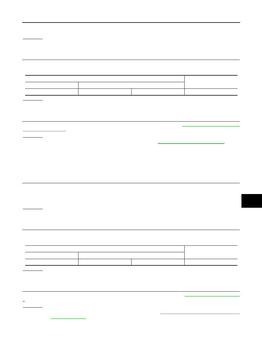
AWD control unit harness connector
Resistance (
Ω
)
Connector No.
Terminal No.
M92
8
16
Approx. 54 – 66
Display control unit harness connector
Resistance (
Ω
)
Connector No.
Terminal No.
M76
25
26
Approx. 54 – 66

LAN-74
< SERVICE INFORMATION >
[CAN]
TROUBLE DIAGNOSIS
NG
>> Repair the power supply and the ground circuit.
ICC Unit Branch Line Circuit
INFOID:0000000001328657
INSPECTION PROCEDURE
1.
CHECK CONNECTOR
1.
Turn the ignition switch OFF.
2.
Disconnect the battery cable from the negative terminal.
3.
Check the terminals and connectors of the ICC unit for damage, bend and loose connection (unit side and
connector side).
OK or NG
OK
>> GO TO 2.
NG
>> Repair the terminal and connector.
2.
CHECK HARNESS FOR OPEN CIRCUIT
1.
Disconnect the connector of ICC unit.
2.
Check the resistance between the ICC unit harness connector terminals.
OK or NG
OK
>> GO TO 3.
NG
>> Repair the ICC unit branch line.
3.
CHECK POWER SUPPLY AND GROUND CIRCUIT
Check the power supply and the ground circuit of the ICC unit. Refer to
OK or NG
OK
>> • Present error: Replace the ICC unit. Refer to
.
• Past error: Error was detected in the ICC unit branch line.
NG
>> Repair the power supply and the ground circuit.
TCM Branch Line Circuit
INFOID:0000000001328658
INSPECTION PROCEDURE
1.
CHECK CONNECTOR
1.
Turn the ignition switch OFF.
2.
Disconnect the battery cable from the negative terminal.
3.
Check the following terminals and connectors for damage, bend, and loose connection (unit side and con-
nector side).
-
A/T assembly
-
Harness connector F102
-
Harness connector M82
OK or NG
OK
>> GO TO 2.
NG
>> Repair the terminal and connector.
2.
CHECK HARNESS FOR OPEN CIRCUIT
1.
Disconnect the connector of A/T assembly.
2.
Check the resistance between the A/T assembly harness connector terminals.
OK or NG
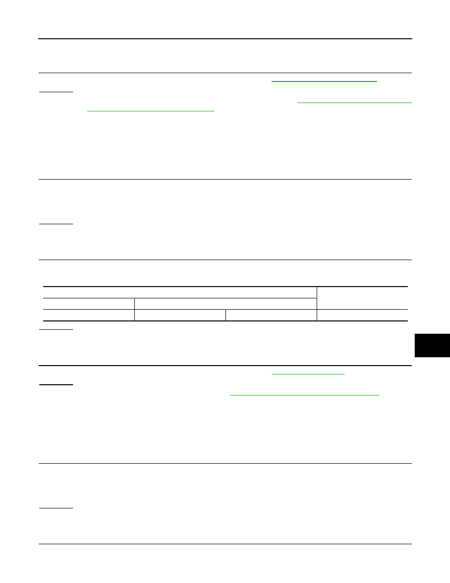
ICC unit harness connector
Resistance (
Ω
)
Connector No.
Terminal No.
M88
14
5
Approx. 54 – 66
A/T assembly harness connector
Resistance (
Ω
)
Connector No.
Terminal No.
F44
3
8
Approx. 54 – 66
TROUBLE DIAGNOSIS
LAN-75
< SERVICE INFORMATION >
[CAN]
C
D
E
F
G
H
I
J
L
M
A
B
LAN
N
O
P
OK
>> GO TO 3.
NG
>> Repair the TCM branch line.
3.
CHECK POWER SUPPLY AND GROUND CIRCUIT
Check the power supply and the ground circuit of the TCM. Refer to
.
OK or NG
OK
>> • Present error: Replace the control valve with TCM. Refer to
AT-215, "Control Valve with TCM
and A/T Fluid Temperature Sensor 2"
• Past error: Error was detected in the TCM branch line.
NG
>> Repair the power supply and the ground circuit.
BCM Branch Line Circuit
INFOID:0000000001328659
INSPECTION PROCEDURE
1.
CHECK CONNECTOR
1.
Turn the ignition switch OFF.
2.
Disconnect the battery cable from the negative terminal.
3.
Check the terminals and connectors of the BCM for damage, bend and loose connection (unit side and
connector side).
OK or NG
OK
>> GO TO 2.
NG
>> Repair the terminal and connector.
2.
CHECK HARNESS FOR OPEN CIRCUIT
1.
Disconnect the connector of BCM.
2.
Check the resistance between the BCM harness connector terminals.
OK or NG
OK
>> GO TO 3.
NG
>> Repair the BCM branch line.
3.
CHECK POWER SUPPLY AND GROUND CIRCUIT
Check the power supply and the ground circuit of the BCM. Refer to
.
OK or NG
OK
>> • Present error: Replace the BCM. Refer to
BCS-13, "Removal and Installation of BCM"
• Past error: Error was detected in the BCM branch line.
NG
>> Repair the power supply and the ground circuit.
Data Link Connector Branch Line Circuit
INFOID:0000000001328660
INSPECTION PROCEDURE
1.
CHECK CONNECTOR
1.
Turn the ignition switch OFF.
2.
Disconnect the battery cable from the negative terminal.
3.
Check the terminals and connectors of the data link connector for damage, bend and loose connection
(connector side and harness side).
OK or NG
OK
>> GO TO 2.
NG
>> Repair the terminal and connector.
2.
CHECK HARNESS FOR OPEN CIRCUIT
Check the resistance between the data link connector terminals.
BCM harness connector
Resistance (
Ω
)
Connector No.
Terminal No.
M3
39
40
Approx. 54 – 66

LAN-76
< SERVICE INFORMATION >
[CAN]
TROUBLE DIAGNOSIS
OK or NG
OK
>> • Present error: Check the following items again.
- Decision of CAN system type.
- Not received CONSULT-III data [SELF-DIAG RESULTS, CAN DIAG SUPPORT MNTR (“ECU
list” included)].
- Not copied from on-board diagnosis.
- Procedure for detecting root cause.
• Past error: Error was detected in the data link connector branch line circuit.
NG
>> Repair the data link connector branch line.
Intelligent Key Unit Branch Line Circuit
INFOID:0000000001328661
INSPECTION PROCEDURE
1.
CHECK CONNECTOR
1.
Turn the ignition switch OFF.
2.
Disconnect the battery cable from the negative terminal.
3.
Check the terminals and connectors of the Intelligent Key unit for damage, bend and loose connection
(unit side and connector side).
OK or NG
OK
>> GO TO 2.
NG
>> Repair the terminal and connector.
2.
CHECK HARNESS FOR OPEN CIRCUIT
1.
Disconnect the connector of Intelligent Key unit.
2.
Check the resistance between the Intelligent Key unit harness connector terminals.
OK or NG
OK
>> GO TO 3.
NG
>> Repair the Intelligent Key unit branch line.
3.
CHECK POWER SUPPLY AND GROUND CIRCUIT
Check the power supply and the ground circuit of the Intelligent Key unit. Refer to
Key Unit Power Supply and Ground Circuit"
OK or NG
OK
>> • Present error: Replace the Intelligent Key unit. Refer to
BL-130, "Removal and Installation of
.
• Past error: Error was detected in the Intelligent Key unit branch line.
NG
>> Repair the power supply and the ground circuit.
LDW Camera Unit Branch Line Circuit
INFOID:0000000001328662
INSPECTION PROCEDURE
1.
CHECK CONNECTOR
1.
Turn the ignition switch OFF.
2.
Disconnect the battery cable from the negative terminal.
3.
Check the following terminals and connectors for damage, bend, and loose connection (unit side and con-
nector side).
-
LDW camera unit
Data link connector
Resistance (
Ω
)
Connector No.
Terminal No.
M5
6
14
Approx. 54 – 66
Intelligent Key unit harness connector
Resistance (
Ω
)
Connector No.
Terminal No.
M34
2
3
Approx. 54 – 66
Нет комментариевНе стесняйтесь поделиться с нами вашим ценным мнением.
Текст