Infiniti FX35 / FX45. Manual — part 773
TROUBLE DIAGNOSIS
LAN-69
< SERVICE INFORMATION >
[CAN]
C
D
E
F
G
H
I
J
L
M
A
B
LAN
N
O
P
SHORT CIRCUIT
Main Line Between TCM and Data Link Connector
INFOID:0000000001328650
INSPECTION PROCEDURE
1.
CHECK HARNESS CONTINUITY (OPEN CIRCUIT)
1.
Turn the ignition switch OFF.
2.
Disconnect the battery cable from the negative terminal.
3.
Disconnect the following harness connectors.
-
ECM
-
Harness connectors M82 and F102
4.
Check the continuity between the harness connector and the data link connector.
OK or NG
OK
>> • Present error: Check the following items again.
- Decision of CAN system type.
- Not received CONSULT-III data [SELF-DIAG RESULTS, CAN DIAG SUPPORT MNTR (“ECU
list” included)].
- Not copied from on-board diagnosis.
- Procedure for detecting root cause.
• Past error: Error was detected in the main line between the TCM and the data link connector.
NG
>> Repair the main line between the harness connector M82 and the data link connector.
Main Line Between Data Link Connector and Unified Meter and A/C Amp.
INFOID:0000000001328651
INSPECTION PROCEDURE
1.
CHECK HARNESS CONTINUITY (OPEN CIRCUIT)
1.
Turn the ignition switch OFF.
2.
Disconnect the battery cable from the negative terminal.
3.
Disconnect the following harness connectors.
-
ECM
-
Unified meter and A/C amp.
4.
Check the continuity between the data link connector and the unified meter and A/C amp. harness con-
nector.
Data link connector branch line circuit
LAN-75, "Data Link Connector Branch Line Circuit"
Intelligent Key unit branch line circuit
LAN-76, "Intelligent Key Unit Branch Line Circuit"
LDW camera unit branch line circuit
LAN-76, "LDW Camera Unit Branch Line Circuit"
Steering angle sensor branch line circuit
LAN-77, "Steering Angle Sensor Branch Line Circuit"
Unified meter and A/C amp. branch line circuit
LAN-78, "Unified Meter and A/C Amp. Branch Line Circuit"
ABS actuator and electric unit (control unit) branch line circuit
LAN-78, "ABS Actuator and Electric Unit (Control Unit) Branch
Line Circuit"
ICC sensor branch line circuit
LAN-79, "ICC Sensor Branch Line Circuit"
Driver seat control unit branch line circuit
LAN-79, "Driver Seat Control Unit Branch Line Circuit"
IPDM E/R branch line circuit
LAN-80, "IPDM E/R Branch Line Circuit"
Malfunction Area
Reference
Malfunction Area
Reference
CAN communication circuit
LAN-81, "CAN Communication Circuit"
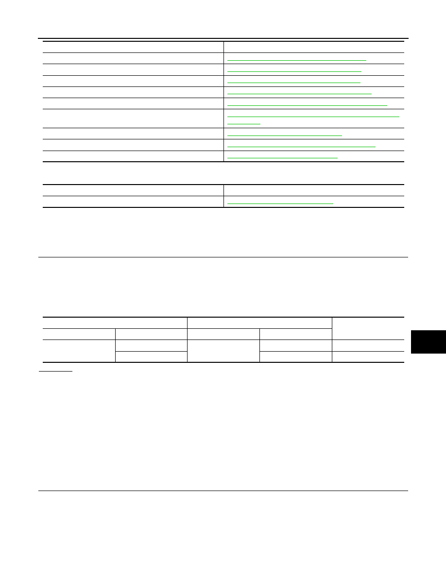
Harness connector
Data link connector
Continuity
Connector No.
Terminal No.
Connector No.
Terminal No.
M82
14H
M5
6
Yes
15H
14
Yes
LAN-70
< SERVICE INFORMATION >
[CAN]
TROUBLE DIAGNOSIS
OK or NG
OK
>> • Present error: Check the following items again.
- Decision of CAN system type.
- Not received CONSULT-III data [SELF-DIAG RESULTS, CAN DIAG SUPPORT MNTR (“ECU
list” included)].
- Not copied from on-board diagnosis.
- Procedure for detecting root cause.
• Past error: Error was detected in the main line between the data link connector and the unified
meter and A/C amp.
NG
>> Repair the main line between the data link connector and the unified meter and A/C amp.
Main Line Between Unified Meter and A/C Amp. and ABS Actuator and Electric Unit
(Control Unit)
INFOID:0000000001328652
INSPECTION PROCEDURE
1.
CHECK CONNECTOR
1.
Turn the ignition switch OFF.
2.
Disconnect the battery cable from the negative terminal.
3.
Check the following terminals and connectors for damage, bend and loose connection (connector side
and harness side).
-
Harness connector M41
-
Harness connector E211
OK or NG
OK
>> GO TO 2.
NG
>> Repair the terminal and connector.
2.
CHECK HARNESS CONTINUITY (OPEN CIRCUIT)
1.
Disconnect the following harness connectors.
-
Unified meter and A/C amp.
-
Harness connectors M41 and E211
2.
Check the continuity between the unified meter and A/C amp. harness connector and the harness con-
nector.
OK or NG
OK
>> GO TO 3.
NG
>> Repair the main line between the unified meter and A/C amp. and the harness connector M41.
3.
CHECK HARNESS CONTINUITY (OPEN CIRCUIT)
1.
Disconnect the connector of ABS actuator and electric unit (control unit).
2.
Check the continuity between the harness connector and the ABS actuator and electric unit (control unit)
harness connector.
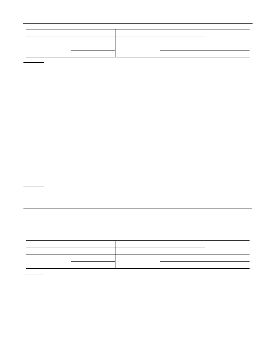
Data link connector
Unified meter and A/C amp. harness connector
Continuity
Connector No.
Terminal No.
Connector No.
Terminal No.
M5
6
M55
1
Yes
14
11
Yes
Unified meter and A/C amp. harness connector
Harness connector
Continuity
Connector No.
Terminal No.
Connector No.
Terminal No.
M55
1
M41
29G
Yes
11
18G
Yes
TROUBLE DIAGNOSIS
LAN-71
< SERVICE INFORMATION >
[CAN]
C
D
E
F
G
H
I
J
L
M
A
B
LAN
N
O
P
OK or NG
OK
>> • Present error: Check the following items again.
- Decision of CAN system type.
- Not received CONSULT-III data [SELF-DIAG RESULTS, CAN DIAG SUPPORT MNTR (“ECU
list” included)].
- Not copied from on-board diagnosis.
- Procedure for detecting root cause.
• Past error: Error was detected in the main line between the unified meter and A/C amp. and the
ABS actuator and electric unit (control unit).
NG
>> Repair the main line between the harness connector E211 and the ABS actuator and electric unit
(control unit).
Main Line Between ABS Actuator and Electric Unit (Control Unit) and Driver Seat Con-
trol Unit
INFOID:0000000001328653
INSPECTION PROCEDURE
1.
CHECK CONNECTOR
1.
Turn the ignition switch OFF.
2.
Disconnect the battery cable from the negative terminal.
3.
Check the following terminals and connectors for damage, bend and loose connection (connector side
and harness side).
-
Harness connector E205
-
Harness connector B5
OK or NG
OK
>> GO TO 2.
NG
>> Repair the terminal and connector.
2.
CHECK HARNESS CONTINUITY (OPEN CIRCUIT)
1.
Disconnect the following harness connectors.
-
ABS actuator and electric unit (control unit)
-
Harness connectors E205 and B5
2.
Check the continuity between the ABS actuator and electric unit (control unit) harness connector and the
harness connector.
OK or NG
OK
>> GO TO 3.
NG
>> Repair the main line between the ABS actuator and electric unit (control unit) and the harness
connector E205.
3.
CHECK HARNESS CONTINUITY (OPEN CIRCUIT)
1.
Disconnect the harness connectors B8 and B151.
2.
Check the continuity between the harness connectors.
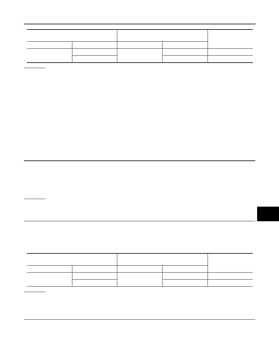
Harness connector
ABS actuator and electric unit (control unit)
harness connector
Continuity
Connector No.
Terminal No.
Connector No.
Terminal No.
E211
29G
E56
11
Yes
18G
15
Yes
ABS actuator and electric unit (control unit)
harness connector
Harness connector
Continuity
Connector No.
Terminal No.
Connector No.
Terminal No.
E56
11
E205
4
Yes
15
10
Yes
LAN-72
< SERVICE INFORMATION >
[CAN]
TROUBLE DIAGNOSIS
OK or NG
OK
>> • Present error: Check the following items again.
- Decision of CAN system type.
- Not received CONSULT-III data [SELF-DIAG RESULTS, CAN DIAG SUPPORT MNTR (“ECU
list” included)].
- Not copied from on-board diagnosis.
- Procedure for detecting root cause.
• Past error: Error was detected in the main line between the ABS actuator and electric unit (con-
trol unit) and the driver seat control unit.
NG
>> Repair the main line between the harness connectors B5 and B8.
ECM Branch Line Circuit
INFOID:0000000001328654
INSPECTION PROCEDURE
1.
CHECK CONNECTOR
1.
Turn the ignition switch OFF.
2.
Disconnect the battery cable from the negative terminal.
3.
Check the terminals and connectors of the ECM for damage, bend and loose connection (unit side and
connector side).
OK or NG
OK
>> GO TO 2.
NG
>> Repair the terminal and connector.
2.
CHECK HARNESS FOR OPEN CIRCUIT
1.
Disconnect the connector of ECM.
2.
Check the resistance between the ECM harness connector terminals.
OK or NG
OK
>> GO TO 3.
NG
>> Repair the ECM branch line.
3.
CHECK POWER SUPPLY AND GROUND CIRCUIT
Check the power supply and the ground circuit of the ECM. Refer to
(VK45DE).
OK or NG
OK
>> • Present error: Replace the ECM. Refer to
EC-100, "Engine Control Component Parts Loca-
EC-677, "Engine Control Component Parts Location"
(VK45DE).
• Past error: Error was detected in the ECM branch line.
NG
>> Repair the power supply and the ground circuit.
AWD Control Unit Branch Line Circuit
INFOID:0000000001328655
INSPECTION PROCEDURE
1.
CHECK CONNECTOR
1.
Turn the ignition switch OFF.
2.
Disconnect the battery cable from the negative terminal.
Harness connector
Harness connector
Continuity
Connector No.
Terminal No.
Connector No.
Terminal No.
B5
4
B8
10
Yes
10
9
Yes
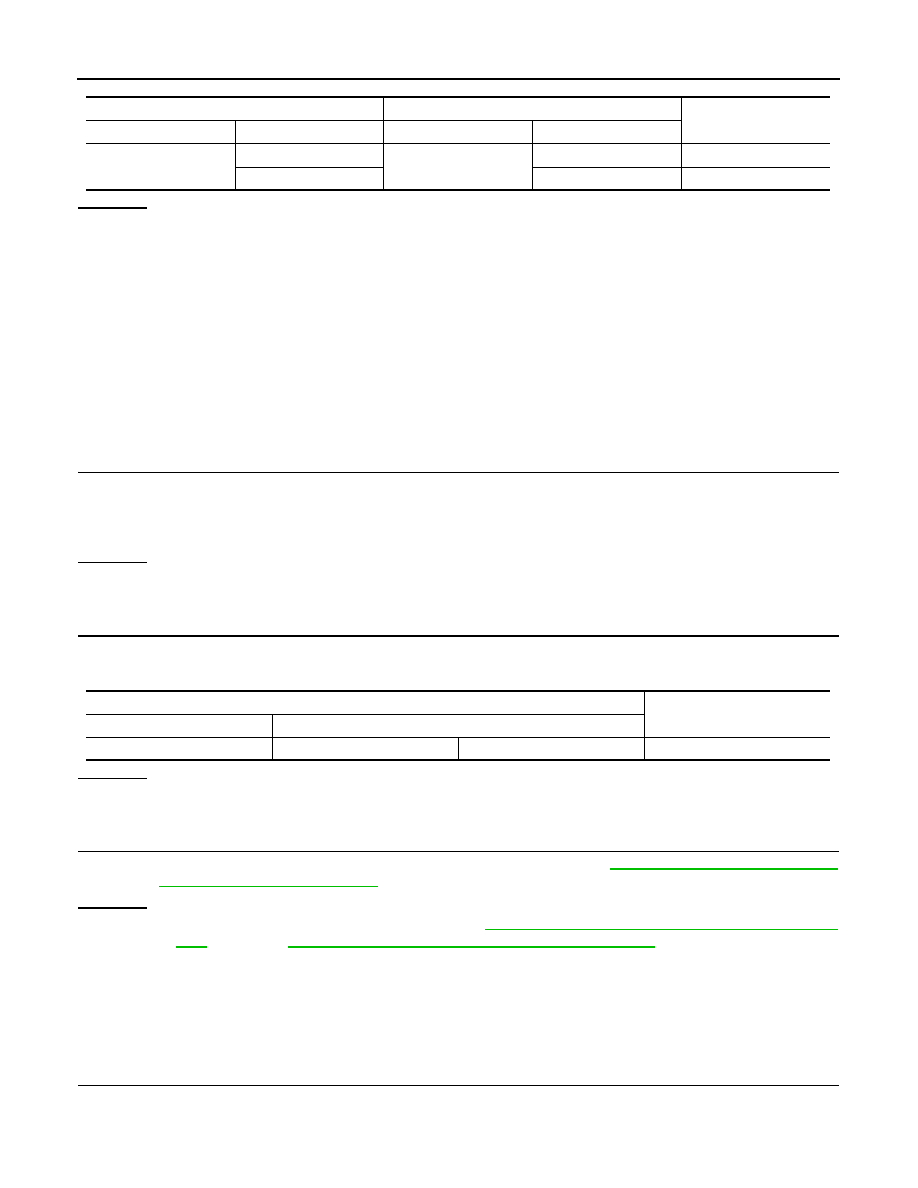
ECM harness connector
Resistance (
Ω
)
Connector No.
Terminal No.
M90
94
86
Approx. 108 – 132
Нет комментариевНе стесняйтесь поделиться с нами вашим ценным мнением.
Текст