Infiniti FX35 / FX45. Manual — part 184
BL-3
C
D
E
F
G
H
J
K
L
M
A
B
BL
N
O
P
Preliminary Check . . . . . . . . . . . . .
Trouble Diagnosis Symptom Chart . . . . . ...
Diagnosis Procedure 1 . . . . . . . . . . ..
Diagnosis Procedure 2 . . . . . . . . . . ..
Diagnosis Procedure 3 . . . . . . . . . . ..
Diagnosis Procedure 4 . . . . . . . . . . ..
Diagnosis Procedure 5 . . . . . . . . . . ..
Diagnosis Procedure 6 . . . . . . . . . . ..
IVIS (INFINITI VEHICLE IMMOBILIZER SYS-
TEM-NATS) . . . . . . . . . . . . . ..
Component Parts and Harness Connector Loca-
tion . . . . . . . . . . . . . . . . . .
System Description . . . . . . . . . . . ...
System Composition . . . . . . . . . . . .
ECM Re-Communicating Function . . . . . .
Wiring Diagram - NATS - . . . . . . . . . ..
Terminal and Reference Value for Steering Lock
Unit/with Intelligent Key System . . . . . . .
Terminal and Reference Value for Intelligent Key
Unit/with Intelligent Key System . . . . . . .
Terminal and Reference Value for BCM . . . ...
CONSULT-III Function . . . . . . . . . . ..
Diagnosis Procedure . . . . . . . . . . . .
Trouble Diagnosis Symptom Chart . . . . . .
Security Indicator Inspection . . . . . . . . .
Diagnosis Procedure 1 . . . . . . . . . . ..
Diagnosis Procedure 2 . . . . . . . . . . ..
Diagnosis Procedure 3 . . . . . . . . . . ..
Diagnosis Procedure 4 . . . . . . . . . . ..
Diagnosis Procedure 5 . . . . . . . . . . ..
Diagnosis Procedure 6 . . . . . . . . . . ..
Removal and Installation NATS Antenna Amp . ..
INTEGRATED HOMELINK TRANSMITTER ..
Wiring Diagram - TRNSCV - . . . . . . . . ..
Trouble Diagnosis . . . . . . . . . . . . ..
BODY REPAIR . . . . . . . . . . . .
Body Exterior Paint Color . . . . . . . . . ..
Body Component Parts . . . . . . . . . . .
Corrosion Protection . . . . . . . . . . . ..
Body Sealing . . . . . . . . . . . . . . .
Body Construction . . . . . . . . . . . . .
Body Alignment . . . . . . . . . . . . . .
Handling Precaution for Plastics . . . . . . .
Precaution in Repairing High Strength Steel . . .

BL-4
< SERVICE INFORMATION >
DTC INDEX
SERVICE INFORMATION
DTC INDEX
INTELLGENT KEY UNIT U1000
INFOID:0000000001529387
INTELLGENT KEY UNIT B2013-B2014
INFOID:0000000001529388
ECM P1610-P1615
INFOID:0000000001529389
CONSULT display
Description
Reference page
U1000: CAN COMM CIRCUIT
Malfunction is detected in CAN communication.
CONSULT display
Description
Reference page
B2013: STRG COMM 1
.Malfunction is detected in communication of Intelligent
Key unit and steering lock unit
BL-124, "Check Steering
Lock Unit"
B2014: STRG COMM 2
Malfunction is detected in communication of Intelligent Key
unit and steering lock unit.
BL-124, "Check Steering
Lock Unit"
CONSULT display
Description
Reference page
P1610: LOCK MODE
When the starting operation is carried out 5 or more times
consecutively under the following conditions, IVIS(NATS)
will shift the mode to prevent the engine start.
• unregistered ignition key is used (without intelligent key
system)
• BCM or ECM malfunctioning
BL-198, "Diagnosis Proce-
dure 5"
P1611: ID DISCORD, IMM-ECM
The result of ID verification between BCM and ECM is NG.
System initialization is required.
BL-197, "Diagnosis Proce-
dure 4"
P1612: CHAIN OF ECM-IMMU
Communication impossible between ECM and BCM.
BL-197, "Diagnosis Proce-
dure 2"
P1613: ECM INT CIRC-IMMU
The malfunction of ECM internal circuit to BCM communi-
cation line is detected.
BL-195, "Diagnosis Proce-
dure 1"
P1614: CHAIN OF IMMU-KEY
BCM cannot receive the key ID signal.
BL-200, "Diagnosis Proce-
dure 6"
P1615: DIFFERENCE OF KEY
BCM can receive the key ID signal but the result of ID ver-
ification between key ID and BCM is NG.
PRECAUTIONS
BL-5
< SERVICE INFORMATION >
C
D
E
F
G
H
J
K
L
M
A
B
BL
N
O
P
PRECAUTIONS
Precaution for Supplemental Restraint System (SRS) "AIR BAG" and "SEAT BELT
PRE-TENSIONER"
INFOID:0000000001612892
The Supplemental Restraint System such as “AIR BAG” and “SEAT BELT PRE-TENSIONER”, used along
with a front seat belt, helps to reduce the risk or severity of injury to the driver and front passenger for certain
types of collision. This system includes seat belt switch inputs and dual stage front air bag modules. The SRS
system uses the seat belt switches to determine the front air bag deployment, and may only deploy one front
air bag, depending on the severity of a collision and whether the front occupants are belted or unbelted.
Information necessary to service the system safely is included in the “SUPPLEMENTAL RESTRAINT SYS-
TEM” and “SEAT BELTS” of this Service Manual.
WARNING:
• To avoid rendering the SRS inoperative, which could increase the risk of personal injury or death in
the event of a collision which would result in air bag inflation, all maintenance must be performed by
an authorized NISSAN/INFINITI dealer.
• Improper maintenance, including incorrect removal and installation of the SRS, can lead to personal
injury caused by unintentional activation of the system. For removal of Spiral Cable and Air Bag
Module, see the “SUPPLEMENTAL RESTRAINT SYSTEM”.
• Do not use electrical test equipment on any circuit related to the SRS unless instructed to in this
Service Manual. SRS wiring harnesses can be identified by yellow and/or orange harnesses or har-
ness connectors.
Precaution Necessary for Steering Wheel Rotation After Battery Disconnect
INFOID:0000000001612889
NOTE:
• This Procedure is applied only to models with Intelligent Key system and NVIS/IVIS (NISSAN/INFINITI
VEHICLE IMMOBILIZER SYSTEM - NATS).
• Remove and install all control units after disconnecting both battery cables with the ignition knob in the
″
LOCK
″
position.
• Always use CONSULT-III to perform self-diagnosis as a part of each function inspection after finishing work.
If DTC is detected, perform trouble diagnosis according to self-diagnostic results.
For models equipped with the Intelligent Key system and NVIS/IVIS, an electrically controlled steering lock
mechanism is adopted on the key cylinder.
For this reason, if the battery is disconnected or if the battery is discharged, the steering wheel will lock and
steering wheel rotation will become impossible.
If steering wheel rotation is required when battery power is interrupted, follow the procedure below before
starting the repair operation.
OPERATION PROCEDURE
1.
Connect both battery cables.
NOTE:
Supply power using jumper cables if battery is discharged.
2.
Use the Intelligent Key or mechanical key to turn the ignition switch to the
″
ACC
″
position. At this time, the
steering lock will be released.
3.
Disconnect both battery cables. The steering lock will remain released and the steering wheel can be
rotated.
4.
Perform the necessary repair operation.
5.
When the repair work is completed, return the ignition switch to the
″
LOCK
″
position before connecting
the battery cables. (At this time, the steering lock mechanism will engage.)
6.
Perform a self-diagnosis check of all control units using CONSULT-III.
Precaution for Work
INFOID:0000000001327777
• After removing and installing the opening/closing parts, be sure to carry out fitting adjustments to check their
operation.
• Check the lubrication level, damage, and wear of each part. If necessary, grease or replace it.
BL-6
< SERVICE INFORMATION >
PREPARATION
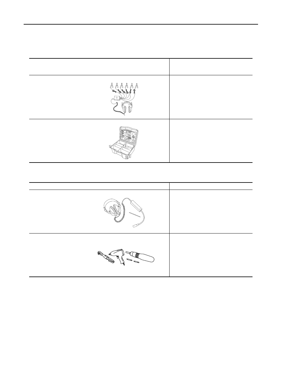
PREPARATION
Special Service Tool
INFOID:0000000001327778
The actual shapes of Kent-Moore tools may differ from those of special service tools illustrated here.
Commercial Service Tool
INFOID:0000000001327779
Tool number
(Kent-Moore No.)
Tool name
Description
(J-39570)
Chassis ear
Locating the noise
(J-43980)
NISSAN Squeak and Rat-
tle Kit
Repairing the cause of the noise
SIIA0993E
SIIA0994E
Tool name
Description
Engine ear
Locating the noise
Power tool
Loosening bolts and nuts
SIIA0995E
PIIB1407E
Нет комментариевНе стесняйтесь поделиться с нами вашим ценным мнением.
Текст