Infiniti FX35 / FX45. Manual — part 183
BCM (BODY CONTROL MODULE)
BCS-13
< SERVICE INFORMATION >
C
D
E
F
G
H
I
J
L
M
A
B
BCS
N
O
P
SELF-DIAG RESULTS
U1000 CAN Communication Circuit
INFOID:0000000001606767
1.
PERFORM SELF DIAGNOSTIC
1.
Turn ignition switch ON and wait for 2 seconds or more.
2.
Check “Self Diagnostic Result” of BCM.
Is “CAN COMM CIRCUIT” displayed?
YES
>> Refer to
LAN-14, "Trouble Diagnosis Flow Chart"
NO
>> Refer to
GI-25, "How to Perform Efficient Diagnosis for an Electrical Incident"
Removal and Installation of BCM
INFOID:0000000001328613
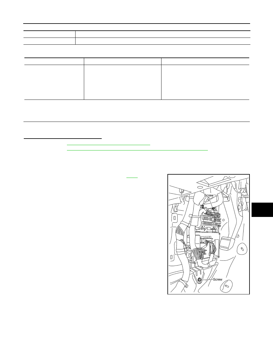
REMOVAL
1.
Remove the dash side finisher (LH). Refer to
2.
Disconnect BCM connector.
3.
Remove bracket mounting screws (3) to remove BCM and fuse
block with bracket.
Item
Description
RESET SETTING VALUE
Return a value set with WORK SUPPORT of each system to a default value in factory shipment.
DTC
DTC Detection Condition
Possible cause
U1000: CAN COMM CIRCUIT
When BCM cannot communicate CAN com-
munication signal continuously for 2 sec-
onds or more.
Any item (or items) of the following listed below is
malfunctioning in CAN communication system.
• Transmission
• Receiving (ECM)
• Receiving (IPDM E/R)
• Receiving (METER/M&A)
• Receiving (I-KEY)
SKIA4964E
BCS-14
< SERVICE INFORMATION >
BCM (BODY CONTROL MODULE)
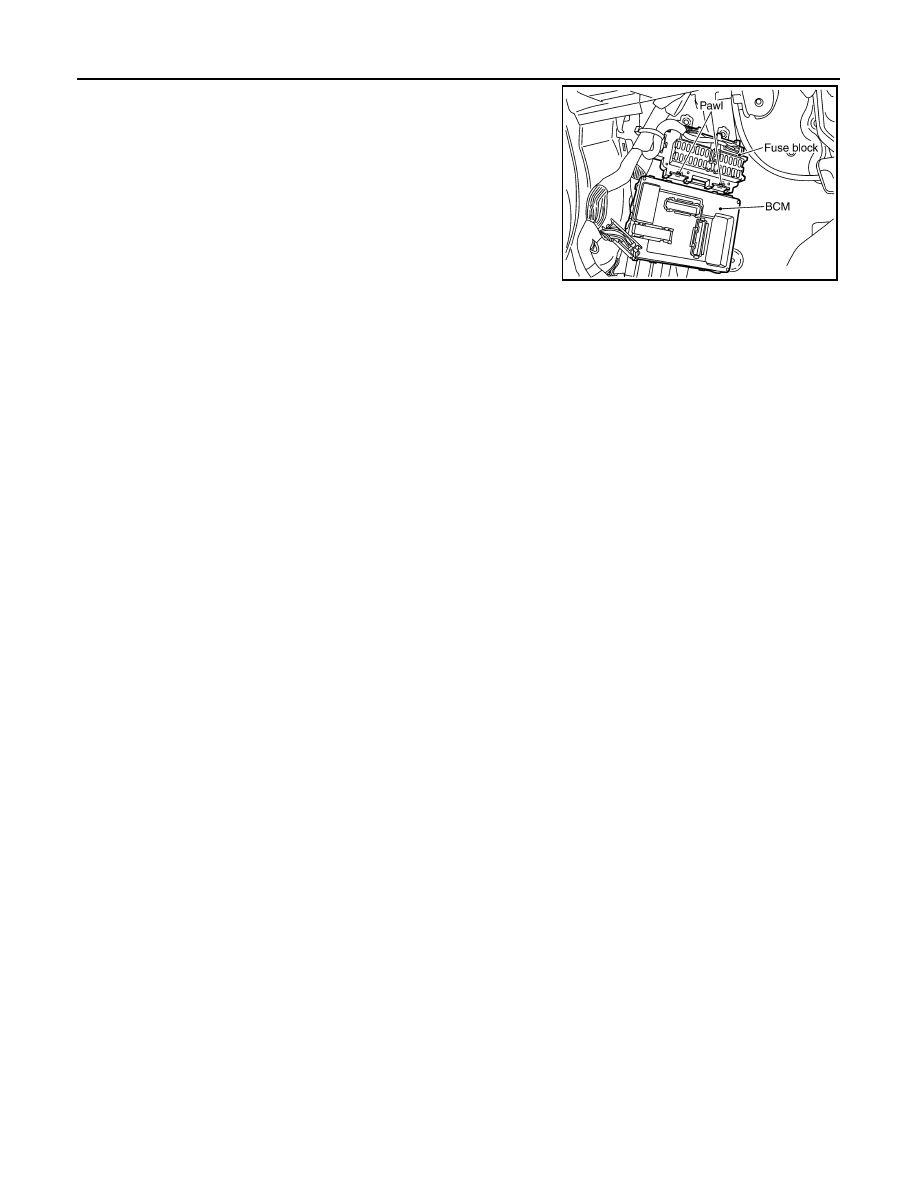
4.
Raise the pawl of fuse block and remove bracket from fuse block
to remove BCM.
INSTALLATION
Installation is the reverse order of removal.
NOTE:
When replacing BCM perform initialization of NATS system and registration of all NATS ignition key IDs.
SKIA4965E
BL-1
BODY
C
D
E
F
G
H
J
K
L
M
SECTION
BL
A
B
BL
N
O
P
CONTENTS
BODY, LOCK & SECURITY SYSTEM
SERVICE INFORMATION . . . . . . .
DTC INDEX . . . . . . . . . . . . . . ..
INTELLGENT KEY UNIT U1000 . . . . . . . ...
INTELLGENT KEY UNIT B2013-B2014 . . . . ...
ECM P1610-P1615 . . . . . . . . . . . . ...
PRECAUTIONS . . . . . . . . . . . . ...
Precaution Necessary for Steering Wheel Rota-
tion After Battery Disconnect . . . . . . . . .....
Precaution for Work . . . . . . . . . . . . ..
PREPARATION . . . . . . . . . . . . ...
Special Service Tool . . . . . . . . . . . .....
Commercial Service Tool . . . . . . . . . . ..
SQUEAK AND RATTLE TROUBLE DIAGNO-
SIS . . . . . . . . . . . . . . . . . ...
Work Flow . . . . . . . . . . . . . . . .....
Generic Squeak and Rattle Troubleshooting . . ....
Diagnostic Worksheet . . . . . . . . . . . .
HOOD . . . . . . . . . . . . . . . . .
Fitting Adjustment . . . . . . . . . . . . ...
Removal and Installation of Hood Assembly . . ...
Removal and Installation of Hood Lock Control . ..
Hood Lock Control Inspection . . . . . . . . .
RADIATOR CORE SUPPORT . . . . . . ...
Removal and Installation . . . . . . . . . . .
FRONT FENDER . . . . . . . . . . . .
Removal and Installation . . . . . . . . . . .
POWER DOOR LOCK SYSTEM . . . . . .
Component Parts and Harness Connector Loca-
tion . . . . . . . . . . . . . . . . . . ..
System Description . . . . . . . . . . . . .
CAN Communication System Description . . . ...
CAN Communication Unit . . . . . . . . . .
Schematic/With Intelligent Key . . . . . . . .
Wiring Diagram - D/LOCK -/With Intelligent Key . .
Schematic/Without Intelligent Key . . . . . . ...
Wiring Diagram - D/LOCK -/Without Intelligent
Key . . . . . . . . . . . . . . . . . . ..
Terminal and Reference Value for BCM . . . . ..
Terminal and Reference Value for Intelligent Key
Unit (With Intelligent Key System) . . . . . . ...
Work Flow . . . . . . . . . . . . . . . .
CONSULT-III Function (BCM) . . . . . . . . .
Trouble Diagnosis Chart by Symptom . . . . . .
Check BCM Power Supply and Ground Circuit . ...
Check Door Switch . . . . . . . . . . . . ..
Check Key Switch . . . . . . . . . . . . .
Check Door Lock and Unlock Switch . . . . . ..
Check Door Lock Actuator (Driver Side) . . . . .
Check Door Lock Actuator (Passenger Side and
Rear LH/RH) . . . . . . . . . . . . . . .
Check Fuel Lid Lock Actuator . . . . . . . . ..
Check Front Door Key Cylinder Switch (Lock) . .
Check Front Door Key Cylinder Switch (Unlock) . .
Check Select Unlock Relay Circuit . . . . . . ..
REMOTE KEYLESS ENTRY SYSTEM . . . .
Component Parts and Harness Connector Loca-
tion . . . . . . . . . . . . . . . . . . ...
System Description . . . . . . . . . . . . ..
CAN Communication System Description . . . ...
CAN Communication Unit . . . . . . . . . .
Schematic . . . . . . . . . . . . . . . .
Wiring Diagram - KEYLES - . . . . . . . . .
Terminal and Reference Value for BCM . . . . ..
Terminal and Reference Value for IPDM E/R . . ..
CONSULT-III Function (BCM) . . . . . . . . .
Work Flow . . . . . . . . . . . . . . . .
Trouble Diagnosis Chart by Symptom . . . . . .
Check Key Fob Battery and Function . . . . . ..
Check ACC Switch . . . . . . . . . . . . ..
Check Door Switch . . . . . . . . . . . . ..
BL-2
Check Remote Keyless Entry Receiver . . . . ..
Check IPDM E/R Operation . . . . . . . . ....
Check Hazard Warning Lamp Function . . . . ..
Check Horn Function . . . . . . . . . . . ..
Check Headlamp Function . . . . . . . . . .
Check Map Lamp and Ignition Keyhole Illumina-
tion Function . . . . . . . . . . . . . . ...
ID Code Entry Procedure . . . . . . . . . ...
Removal and Installation of Remote keyless Entry
receiver . . . . . . . . . . . . . . . . ...
Key Fob Battery Replacement . . . . . . . ....
INTELLIGENT KEY SYSTEM . . . . . . .
Component Parts and Harness Connector Loca-
tion . . . . . . . . . . . . . . . . . . ..
System Description . . . . . . . . . . . . .
CAN Communication System Description . . . ..
CAN Communication Unit . . . . . . . . . ...
Schematic . . . . . . . . . . . . . . . ...
Wiring Diagram - I/KEY - . . . . . . . . . ....
Terminal and Reference Value for INTELLIGENT
KEY UNIT . . . . . . . . . . . . . . . ...
Terminal and Reference Value for Steering Lock
unit . . . . . . . . . . . . . . . . . . .
Terminal and Reference Value for BCM . . . .
Terminal and Reference Value for IPDM E/R . .
Diagnosis Procedure . . . . . . . . . . . .
CONSULT-III Functions (INTELLIGENT KEY) . ..
CONSULT-III Application Item . . . . . . . ...
List of Operation Related Parts . . . . . . . .
Trouble Diagnosis Symptom Chart . . . . . .
Check CAN Communication System Inspection .
Check Intelligent Key Unit Power Supply and
Ground Circuit . . . . . . . . . . . . . ...
Check Key Switch (Intelligent Key Unit Input) . ...
Check Key Switch (BCM Input) . . . . . . . .
Check Ignition Knob Switch . . . . . . . . ...
Check Door Switch . . . . . . . . . . . .
Check Unlock Sensor . . . . . . . . . . .
Check Door Request Switch . . . . . . . . ..
Check Intelligent Key Warning Buzzer . . . . ..
Check Outside Key Antenna . . . . . . . . .
Check Inside Key Antenna . . . . . . . . .
Check Steering Lock Unit . . . . . . . . . ..
Check Stop Lamp Switch . . . . . . . . . ..
Check Park Position Switch . . . . . . . . ...
Check Select Unlock Relay . . . . . . . . ...
Check Hazard Function . . . . . . . . . . .
Check Horn Function . . . . . . . . . . . .
Check Headlamp Function . . . . . . . . .
Check IPDM E/R Operation . . . . . . . . ...
Removal and Installation of Intelligent Key Unit .
Intelligent Key Battery Replacement . . . . . .
DOOR . . . . . . . . . . . . . . . ...
Fitting Adjustment . . . . . . . . . . . . ..
Removal and Installation of Front Door . . . . .
Removal and Installation of Rear Door . . . . ..
Removal and Installation of Door Weatherstrip . .
FRONT DOOR LOCK . . . . . . . . . ...
Removal and Installation . . . . . . . . . ...
REAR DOOR LOCK . . . . . . . . . . .
Removal and Installation . . . . . . . . . ...
BACK DOOR . . . . . . . . . . . . .
Fitting Adjustment . . . . . . . . . . . . .
Back Door Assembly . . . . . . . . . . . .
Removal and Installation of Back Door Striker . .
Removal and Installation of Back Door Stay . . .
Removal and Installation of Dave Tail Male & Fe-
male . . . . . . . . . . . . . . . . . ..
Removal and Installation of Back Door Weather-
strip . . . . . . . . . . . . . . . . . ...
BACK DOOR LOCK ASSEMBLY . . . . .
Removal and Installation of Back Door Lock &
Closure Assembly . . . . . . . . . . . . .
Removal and Installation of Back Door Opener
Switch . . . . . . . . . . . . . . . . ...
Disassembly and Assembly . . . . . . . . ..
BACK DOOR AUTO CLOSURE SYSTEM . ..
Component Parts and Harness Connector Loca-
tion . . . . . . . . . . . . . . . . . .
System Description . . . . . . . . . . . ...
Wiring Diagram - B/CLOS - . . . . . . . . ...
Terminal and Reference Value for Back Door Clo-
sure Control Unit . . . . . . . . . . . . ...
Work Flow . . . . . . . . . . . . . . . .
Preliminary Check . . . . . . . . . . . . .
Trouble Diagnosis Chart by Symptom . . . . ..
Check Back Door Closure Control Unit Power
Supply and Ground Circuit . . . . . . . . .
Check Half-Latch Switch . . . . . . . . . ...
Check Close Switch . . . . . . . . . . . ..
Check Open Switch . . . . . . . . . . . ..
Check Back Door Opener Switch (With Intelligent
Key) . . . . . . . . . . . . . . . . . ...
Check Back Door Opener Switch (Without Intelli-
gent Key) . . . . . . . . . . . . . . . ...
Check Unlock Sensor (Without Intelligent Key) .
Check Closure Motor . . . . . . . . . . .
Removal and Installation of Back Door Closer
Control Unit . . . . . . . . . . . . . . ...
VEHICLE SECURITY (THEFT WARNING)
SYSTEM . . . . . . . . . . . . . . ...
Component Parts and Harness Connector Loca-
tion . . . . . . . . . . . . . . . . . .
System Description . . . . . . . . . . . ...
CAN Communication System Description . . .
CAN Communication Unit . . . . . . . . . .
Schematic . . . . . . . . . . . . . . . .
Wiring Diagram - VEHSEC - . . . . . . . . .
Terminal and Reference Value for BCM . . . ...
Terminal and Reference Value for IPDM E/R . ...
CONSULT-III Function . . . . . . . . . . ..
Нет комментариевНе стесняйтесь поделиться с нами вашим ценным мнением.
Текст