Infiniti FX35 / FX45. Manual — part 565

DTC P1140, P1145 IVT CONTROL POSITION SENSOR
EC-1021
< SERVICE INFORMATION >
[VK45DE]
C
D
E
F
G
H
I
J
K
L
M
A
EC
N
P
O
Do not use ECM ground terminals when measuring input/output voltage. Doing so may result in dam-
age to the ECM's transistor. Use a ground other than ECM terminals, such as the ground.
: Average voltage for pulse signal (Actual pulse signal can be confirmed by oscilloscope.)
TER-
MI-
NAL
NO.
WIRE
COLOR
ITEM
CONDITION
DATA (DC Voltage)
72
BR
Intake valve timing control
position sensor (Bank 1)
[Engine is running]
• Warm-up condition
• Idle speed
0 - 1.0V
[Engine is running]
• Engine speed: 2,000rpm
0 - 1.0V
111
W/B
ECM relay
(Self shut-off)
[Engine is running]
[Ignition switch: OFF]
• For a few seconds after turning ignition
switch OFF
0 - 1.5V
[Ignition switch: OFF]
• More than a few seconds after turning igni-
tion switch OFF
BATTERY VOLTAGE
(11 - 14V)
119
120
R
R/B
Power supply for ECM
[Ignition switch: ON]
BATTERY VOLTAGE
(11 - 14V)
PBIB2046E
EC-1022
< SERVICE INFORMATION >
[VK45DE]
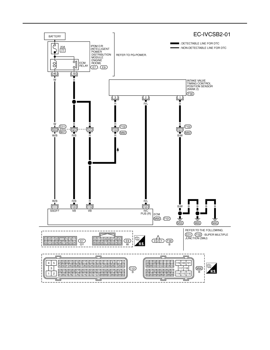
DTC P1140, P1145 IVT CONTROL POSITION SENSOR
BANK 2
Specification data are reference values and are measured between each terminal and ground.
Pulse signal is measured by CONSULT-III.
CAUTION:
Do not use ECM ground terminals when measuring input/output voltage. Doing so may result in dam-
age to the ECM's transistor. Use a ground other than ECM terminals, such as the ground.
TBWM1348E
DTC P1140, P1145 IVT CONTROL POSITION SENSOR
EC-1023
< SERVICE INFORMATION >
[VK45DE]
C
D
E
F
G
H
I
J
K
L
M
A
EC
N
P
O
: Average voltage for pulse signal (Actual pulse signal can be confirmed by oscilloscope.)
Diagnosis Procedure
INFOID:0000000001326884
1.
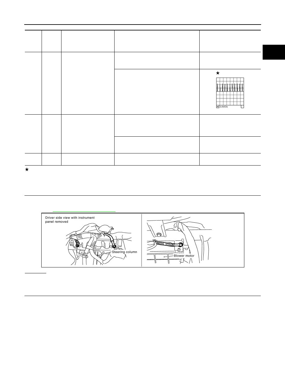
CHECK GROUND CONNECTIONS
1.
Turn ignition switch OFF.
2.
Loosen and retighten three ground screws on the body.
Refer to
OK or NG
OK
>> GO TO 2.
NG
>> Repair or replace ground connections.
2.
CHECK INTAKE VALVE TIMING CONTROL POSITION SENSOR POWER SUPPLY CIRCUIT
TER-
MI-
NAL
NO.
WIRE
COLOR
ITEM
CONDITION
DATA (DC Voltage)
53
R/L
Intake valve timing control
position sensor (Bank 2)
[Engine is running]
• Warm-up condition
• Idle speed
0 - 1.0V
[Engine is running]
• Engine speed: 2,000 rpm
0 - 1.0V
111
W/B
ECM relay
(Self shut-off)
[Engine is running]
[Ignition switch: OFF]
• For a few seconds after turning ignition
switch OFF
0 - 1.5V
[Ignition switch: OFF]
• More than a few seconds after turning igni-
tion switch OFF
BATTERY VOLTAGE
(11 - 14V)
119
120
R
R/B
Power supply for ECM
[Ignition switch: ON]
BATTERY VOLTAGE
(11 - 14V)
PBIB2046E
PBIB2195E
EC-1024
< SERVICE INFORMATION >
[VK45DE]
DTC P1140, P1145 IVT CONTROL POSITION SENSOR
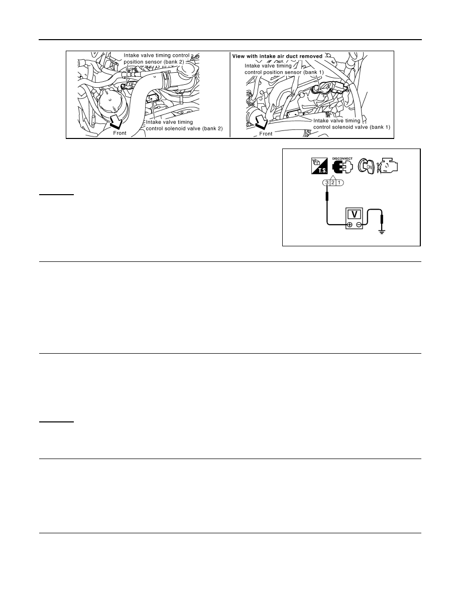
1.
Disconnect intake valve timing control position sensor harness connector.
2.
Turn ignition switch ON.
3.
Check voltage between intake valve timing control position sen-
sor terminal 3 and ground with CONSULT-III or tester.
OK or NG
OK
>> GO TO 4.
NG
>> GO TO 3.
3.
DETECT MALFUNCTIONING PART
Check the following.
• Harness connectors E211, M41
• Harness connectors F102, M82
• Harness for open or short between intake valve timing control position sensor and IPDM E/R
• Harness for open or short between intake valve timing control position sensor and ECM
>> Repair open circuit or short to ground or short to power in harness or connectors.
4.
CHECK INTAKE VALVE TIMING CONTROL POSITION SENSOR GROUND CIRCUIT FOR OPEN AND
SHORT
1.
Turn ignition switch OFF.
2.
Check harness continuity between intake valve timing control position sensor terminal 1 and ground.
Refer to Wiring Diagram.
3.
Also check harness for short to power.
OK or NG
OK
>> GO TO 6.
NG
>> GO TO 5.
5.
DETECT MALFUNCTIONING PART
Check the following.
• Harness connectors F102, M82
• Harness for open or short between intake valve timing control position sensor and ground
>> Repair open circuit or short to power in harness or connectors.
6.
CHECK INTAKE VALVE TIMING CONTROL POSITION SENSOR INPUT SIGNAL CIRCUIT FOR OPEN
AND SHORT
1.
Disconnect ECM harness connector.
2.
Check harness continuity between the following;
ECM terminal 72 and intake valve timing control position sensor (Bank 1) terminal 2 or
ECM terminal 53 and intake valve timing control position sensor (Bank 2) terminal 2.
Voltage: Battery voltage
PBIB1517E
SEF509Y
Continuity should exist.
Нет комментариевНе стесняйтесь поделиться с нами вашим ценным мнением.
Текст