Infiniti FX35 / FX45. Manual — part 564

DTC P0850 PNP SWITCH
EC-1017
< SERVICE INFORMATION >
[VK45DE]
C
D
E
F
G
H
I
J
K
L
M
A
EC
N
P
O
Diagnosis Procedure
INFOID:0000000001326878
1.
CHECK DTC WITH TCM
AT-38, "OBD-II Diagnostic Trouble Code (DTC)"
OK or NG
OK
>> GO TO 2.
NG
>> Repair or replace.
2.
CHECK STARTING SYSTEM
Turn ignition switch OFF, then turn it to START.
Does starter motor operate?
Yes or No
Yes
>> GO TO 3.
No
>> Refer to
.
3.
CHECK PNP SWITCH INPUT SIGNAL CIRCUIT FOR OPEN AND SHORT-I
1.
Turn ignition switch OFF.
2.
Disconnect A/T assembly harness connector.
3.
Disconnect “unified meter and A/C amp.” harness connector.
4.
Check harness continuity between A/T assembly terminal 9 and “unified meter and A/C amp.” terminal 32.
Refer to Wiring Diagram.
5.
Also check harness for short to ground and short to power.
OK or NG
OK
>> GO TO 5.
NG
>> GO TO 4.
4.
DETECT MALFUNCTIONING PART
Check the following.
• Harness connectors F102, M82
• Harness for open or short between A/T assembly and “unified meter and A/C amp.”
>> Repair open circuit or short to ground or short to power in harness or connectors.
5.
CHECK PNP SWITCH INPUT SIGNAL CIRCUIT FOR OPEN AND SHORT-II
1.
Disconnect ECM harness connector.
2.
Check harness continuity between ECM terminal 102 and “unified meter and A/C amp.” terminal 25.
Refer to Wiring Diagram.
3.
Also check harness for short to ground and short to power.
OK or NG
OK
>> GO TO 6.
NG
>> Repair open circuit or short to ground or short to power in harness or connectors.
6.
CHECK PNP SWITCH INPUT SIGNAL CIRCUIT FOR OPEN AND SHORT-III
TER-
MI-
NAL
NO.
WIRE
COLOR
ITEM
CONDITION
DATA (DC Voltage)
102
LG/B
PNP switch
[Ignition switch: ON]
• Selector lever: P or N
Approximately 0V
[Ignition switch: ON]
• Selector lever: Except above
BATTERY VOLTAGE
(11 - 14V)
Continuity should exist.
Continuity should exist.
EC-1018
< SERVICE INFORMATION >
[VK45DE]
DTC P0850 PNP SWITCH
1.
Check harness continuity between A/T assembly terminal 9 and TCM terminal 8.
Refer to
2.
Also check harness for short to ground and short to power.
OK or NG
OK
>> GO TO 7.
NG
>> Repair open circuit or short to ground or short to power in harness or connectors.
7.
CHECK INTERMITTENT INCIDENT
OK or NG
OK
>> GO TO 8.
NG
>> Repair or replace.
8.
REPLACE “UNIFIED METER AND A/C AMP.”
>> INSPECTION END
Continuity should exist.
DTC P1140, P1145 IVT CONTROL POSITION SENSOR
EC-1019
< SERVICE INFORMATION >
[VK45DE]
C
D
E
F
G
H
I
J
K
L
M
A
EC
N
P
O
DTC P1140, P1145 IVT CONTROL POSITION SENSOR
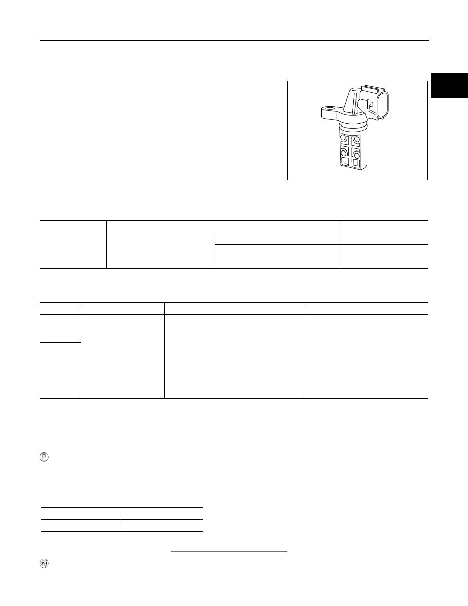
Component Description
INFOID:0000000001326879
Intake valve timing control position sensors are located in the front of
cylinder heads in both bank 1 and bank 2.
This sensor uses a Hall IC.
The cam position is determined by the intake camshaft sprocket con-
cave (in four places). The ECM provides feedback to the intake valve
timing control for appropriate target valve open-close timing accord-
ing to drive conditions based on detected cam position.
CONSULT-III Reference Value in Data Monitor Mode
INFOID:0000000001326880
Specification data are reference values.
On Board Diagnosis Logic
INFOID:0000000001326881
DTC Confirmation Procedure
INFOID:0000000001326882
NOTE:
If DTC Confirmation Procedure has been previously conducted, always turn ignition switch OFF and wait at
least 10 seconds before conducting the next test.
WITH CONSULT-III
1.
Turn ignition switch ON.
2.
Select “DATA MONITOR” mode with CONSULT-III.
3.
Start engine and drive vehicle under the following conditions for at least 10 seconds.
4.
Check 1st trip DTC.
5.
If 1st trip DTC is detected, go to
EC-1023, "Diagnosis Procedure"
WITH GST
Follow the procedure “WITH CONSULT-III” above.
SEF359Z
MONITOR ITEM
CONDITION
SPECIFICATION
INT/V TIM (B1)
INT/V TIM (B2)
• Engine: After warming up
• Selector lever: P or N
• Air conditioner switch: OFF
• No load
Idle
−
5
°
- 5
°
CA
2,000 rpm
Approx. 0
°
- 20
°
CA
DTC No.
Trouble diagnosis name
DTC detecting condition
Possible cause
P1140
1140
(Bank 1)
Intake valve timing control
position sensor circuit
An excessively high or low voltage from the
sensor is sent to ECM.
• Harness or connectors
(Intake valve timing control position
sensor circuit is open or shorted)
• Intake valve timing control position
sensor
• Crankshaft position sensor (POS)
• Camshaft position sensor (PHASE)
• Accumulation of debris to the signal
pick-up portion of the camshaft sprock-
et
P1145
1145
(Bank 2)
ENG SPEED
More than idle speed
Selector lever
P or N position
EC-1020
< SERVICE INFORMATION >
[VK45DE]
DTC P1140, P1145 IVT CONTROL POSITION SENSOR
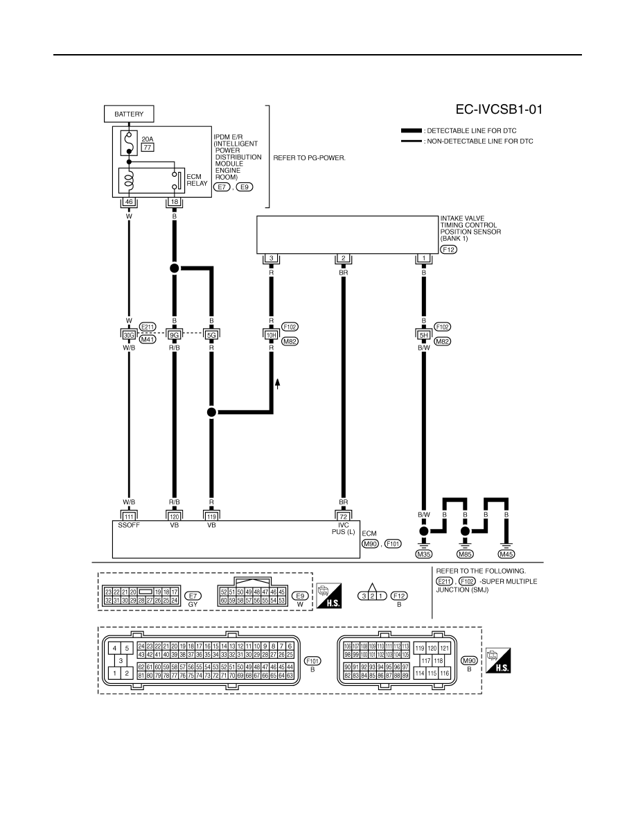
Wiring Diagram
INFOID:0000000001326883
BANK 1
Specification data are reference values and are measured between each terminal and ground.
Pulse signal is measured by CONSULT-III.
CAUTION:
TBWM1347E
Нет комментариевНе стесняйтесь поделиться с нами вашим ценным мнением.
Текст