Infiniti FX35 / FX45. Manual — part 919

SE-34
< SERVICE INFORMATION >
AUTOMATIC DRIVE POSITIONER
Terminal and Reference Value for Driver Seat Control Unit
INFOID:0000000001328105
30
W/R
Passenger side mirror motor
DOWN signal
Output
When passenger side mirror motor
downward
1.5 - Battery voltage
Other than above
0
Passenger side mirror motor
RIGTH signal
When passenger side mirror motor
RIGHT operation
1.5 - Battery voltage
Other than above
0
31
R/W
Driver side mirror motor
UP signal
Output
When driver side mirror motor up-
ward
1.5 - Battery voltage
Other than above
0
32
G/B
Driver side mirror motor
LEFT signal
Output
When driver side mirror motor
LEFT operation
1.5 - Battery voltage
Other than above
0
33
G/W
Sensor power supply
Input
—
5
34
L/R
Battery power supply
Input
—
Battery voltage
35
R/L
Tilt motor UP signal
Output
Tilt switch turned to upward
Battery voltage
Other than above
0
36
L/R
Telescopic motor
FORWARD signal
Output
Telescopic switch turned to for-
ward
Battery voltage
OFF
0
39
W/R
Battery power supply
Input
—
Battery voltage
40
B
Ground (signal)
—
—
0
41
B/Y
Ground (sensor)
—
—
0
42
R/B
Tilt motor DOWN signal
Output
Tilt switch turned to downward
Battery voltage
Other than above
0
44
L/W
Telescopic motor
BACKWARD signal
Output
Telescopic switch turned to back-
ward
Battery voltage
Other than above
0
48
B
Ground (power)
—
—
0
Ter-
minal
Wire
Color
Item
Signal
Input/Output
Condition
Voltage (V)
(Approx.)
Ter-
minal
Wire
Color
Item
Signal Input/
Output
Condition
Voltage (V)
(Approx.)
1A
R
Power source (Fusible link)
Input
—
Battery voltage
2
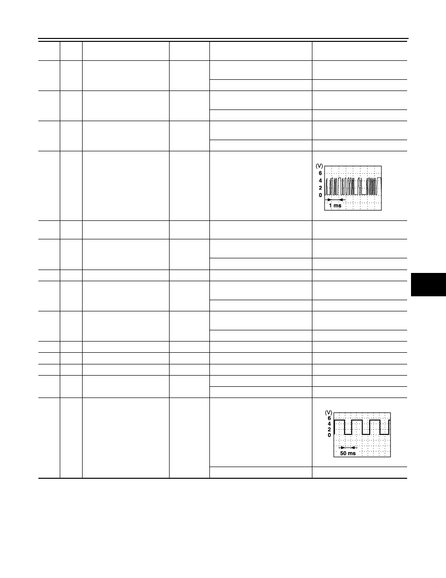
P
UART LINE (TX)
Output
Memory switch 1 or 2 operated
3
G
Sliding motor
FORWARD signal
Output
When sliding motor
FORWARD operation
Battery voltage
Other than above
0
4
G/L
Reclining motor
FORWARD signal
Output
When reclining motor
FORWARD operation
Battery voltage
Other than above
0
PIIA4814E
AUTOMATIC DRIVE POSITIONER
SE-35
< SERVICE INFORMATION >
C
D
E
F
G
H
J
K
L
M
A
B
SE
N
O
P
5
LG
Front lifting motor
DOWN signal
Output
When front lifting motor
DOWN operation
Battery voltage
Other than above
0
6
G/W
Rear lifting motor UP signal
Output
When rear lifting motor
UP operation
Battery voltage
Other than above
0
7
G/B
Rear lifting motor
DOWN signal
Output
When rear lifting motor
DOWN operation
Battery voltage
Other than above
0
8
G/Y
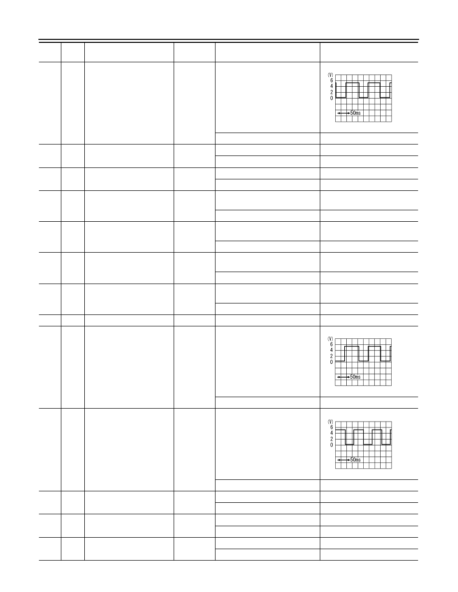
UART LINE (RX)
Input
Memory switch 1 or 2 switch oper-
ated
9
BR
Ignition switch (START)
Input
Ignition switch
(START position)
Battery voltage
10
G/R
Sliding motor
BACKWARD signal
Output
When sliding motor
BACKWARD operation
Battery voltage
Other than above
0
11A
R/W
Power source (Fuse)
Input
—
Battery voltage
12
G/Y
Reclining motor
BACKWARD signal
Output
When reclining motor
BACKWARD operation
Battery voltage
Other than above
0
13
Y
Front lifting motor UP signal
Output
When front lifting motor
UP operation
Battery voltage
Other than above
0
14
OR
CAN-H
Input/Output
—
—
15
SB
CAN-L
Input/Output
—
—
16A
B
Ground (power)
—
—
0
17
PU
Park position switch signal
Input
Selector lever other than P position
Battery voltage
Selector lever is sifted to P position
0
18
G/L
Seat sliding sensor signal
Input
ON (sliding motor operation)
Other than above
0 or 5
Ter-
minal
Wire
Color
Item
Signal Input/
Output
Condition
Voltage (V)
(Approx.)
PIIA4813E
PIIA3277E
SE-36
< SERVICE INFORMATION >
AUTOMATIC DRIVE POSITIONER
19
G/R
Front lifting sensor signal
Input
ON (front lifting motor operation)
Other than above
0 or 5
22
R/B
Power seat memory switch 1
signal
Input
Memory switch 1: ON
0
Memory switch 1: OFF
5
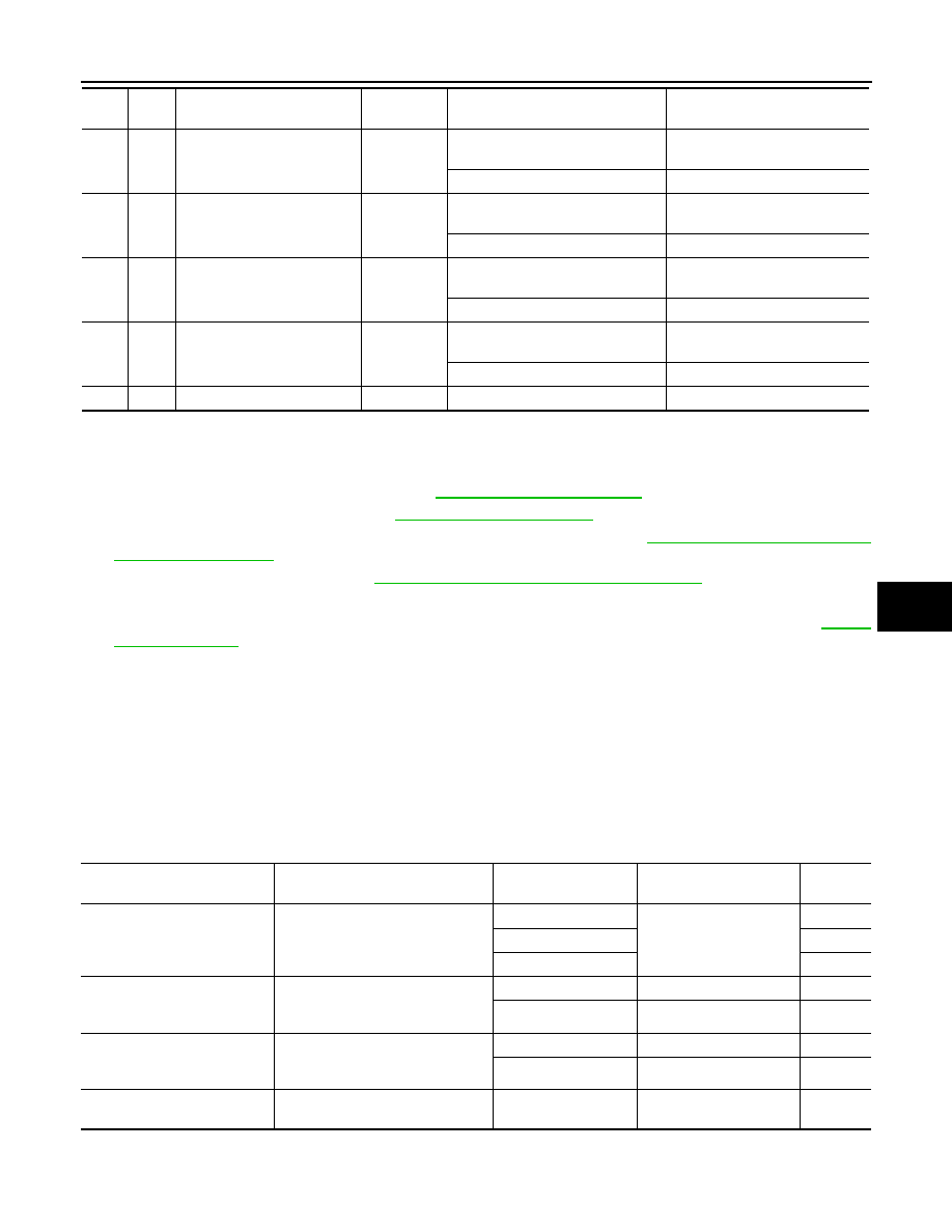
23
Y/W
Power seat memory switch in-
dictor 1 signal
Output
Memory switch 1: ON
1
Memory switch 1: OFF
Battery voltage
24
L/R
Seat sliding switch
FORWARD signal
Input
When seat sliding switch
FORWARD operation
0
Other than above
Battery voltage
25
L/OR
Seat reclining switch
FORWARD signal
Input
When seat reclining switch
FORWARD operation
0
Other than above
Battery voltage
26
L/P
Front lifting switch UP signal
Input
When front lifting switch
UP operation
0
Other than above
Battery voltage
27
L
Rear lifting switch UP signal
Input
When rear lifting switch
UP operation
0
Other than above
Battery voltage
28C
B/W
Ground (sensor)
—
—
0
29
G
Reclining sensor signal
Input
ON (reclining motor operation)
Other than above
0 or 5
30
R/W
Rear lifting sensor signal
Input
ON (rear lifting motor operation)
Other than above
0 or 5
34
L/W
Set switch signal
Input
Set witch: ON
0
Set witch: OFF
5
35
L/B
Power seat memory switch 2
signal
Input
Memory switch 2: ON
0
Memory switch 2: OFF
5
36
Y/G
Power seat memory switch in-
dictor 2 signal
Output
Memory switch 2: ON
1
Memory switch 2: OFF
Battery voltage
Ter-
minal
Wire
Color
Item
Signal Input/
Output
Condition
Voltage (V)
(Approx.)
SIIA0691J
SIIA0692J
SIIA0693J
AUTOMATIC DRIVE POSITIONER
SE-37
< SERVICE INFORMATION >
C
D
E
F
G
H
J
K
L
M
A
B
SE
N
O
P
Work Flow
INFOID:0000000001328106
1.
Check the symptom and customer's requests.
2.
Understand the system description. Refer to
.
3.
Perform the preliminary check, refer to
.
4.
Perform the CAN communication inspection using CONSULT-III, refer to
5.
Perform the self-diagnosis. Refer to
SE-42, "Check CAN Communication System"
6.
Repair or replace depending on the self-diagnostic results.
7.
Based on the trouble diagnosis chart, repair or replace the cause of the malfunction. Refer to
.
8.
Does the automatic drive positioner system operate normally?
If it is normal, GO TO 8.
If it is not normal, GO TO 3.
9.
INSPECTION END
Preliminary Check
INFOID:0000000001328107
SETTING CHANGE FUNCTION
The settings of the automatic driving positioner system can be changed, using CONSULT-III and the display
unit in the center of the instrument panel.
×
: Applicable –: Not applicable
It is possible to set sliding driver seat for entry/exit of vehicle by pressing set switch.
37
W
Seat sliding switch
BACKWARD signal
Input
When seat sliding switch
BACKWARD operation
0
Other than above
Battery voltage
38
LG/B
Seat reclining switch
BACKWARD signal
Input
When seat reclining switch
BACKWARD operation
0
Other than above
Battery voltage
39
L/G
Front lifting switch
DOWN signal
Input
When front lifting switch
DOWN operation
0
Other than above
Battery voltage
40
L/Y
Rear lifting switch
DOWN signal
Input
When rear lifting switch
DOWN operation
0
Other than above
Battery voltage
61E
B/Y
Ground (signal)
—
—
0
Ter-
minal
Wire
Color
Item
Signal Input/
Output
Condition
Voltage (V)
(Approx.)
Setting item
Content
CONSULT-III
(WORK SUPPORT)
Display unit
Factory
setting
Change seat sliding volume
setting
The distance at retain operation can
be selected from the following 3
modes.
40 mm
—
×
80 mm
—
150 mm
—
Change the Entry/Exit seat
slide function setting
The seat sliding turnout and return
at entry/exit can be selected: ON
(operated) – OFF (not operated)
ON
ON: Indicator lamp ON
×
OFF
OFF: Indicator lamp OFF
—
Change the Entry/Exit tilt steer-
ing wheel function setting
Tilt up and backward steering wheel
at entry and exit can be selected:
ON (operated) - OFF (not operated)
ON
ON: Indicator lamp ON
×
OFF
OFF: Indicator lamp OFF
—
Reset custom settings
All settings to default.
—
Default: Setting button
OFF
—
Нет комментариевНе стесняйтесь поделиться с нами вашим ценным мнением.
Текст