Infiniti FX35 / FX45. Manual — part 920
SE-38
< SERVICE INFORMATION >
AUTOMATIC DRIVE POSITIONER
NOTE:
After the setting is registered, the new setting is effective, even if the battery is disconnected.
CHECK POWER SUPPLY AND GROUND
1.
CHECK FUSE
Check if any of the following fuses in the BCM are blown.
• Check 50A fusible link (letter M, located in the fuse and fusible link box.)
• Check 15A fuse [No.22, located in the fuse block (J/B)]
• Check 10A fuse [No.1, located in the fuse block (J/B)]
• Check 10A fuse [No.6, located in the fuse block (J/B)]
NOTE:
Refer to
SE-16, "Component Parts and Harness Connector Location"
OK or NG
OK
>> GO TO 2.
NG
>> If fuse is blown out, be sure to eliminate cause of malfunction before installing new fuse. Refer to
SE-16, "Component Parts and Harness Connector Location"
2.
CHECK POWER SUPPLY CIRCUIT (BCM)
1.
Turn ignition switch OFF.
2.
Disconnect BCM connector.
3.
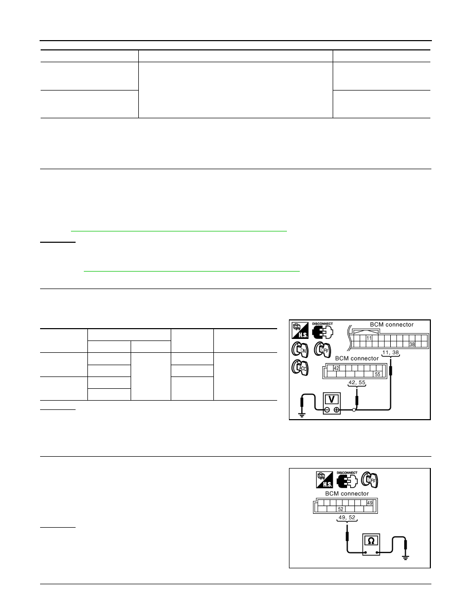
Check voltage between BCM connector and ground.
OK or NG
OK
>> GO TO 3.
NG
>> Check harness for open and short between BCM and
fuse or fusible link.
3.
CHECK GROUND CIRCUIT (BCM)
1.
Turn ignition switch OFF.
2.
Check continuity between BCM connector M4 terminal 49, 52
and ground.
OK or NG
OK
>> BCM circuit is OK. Check the driver seat control unit.
GO TO 4.
NG
>> Repair or replace the harness between BCM and
ground.
4.
CHECK FUSE
Content
Setting change operation
Indicator LED
The seat sliding turnout and
steering wheel up/backward at
entry/exit can be operated.
Press the set switch for more than 10 seconds
Blinking twice
The seat sliding turnout and
steering wheel up/backward at
entry/exit can be not operated.
Blinking ones
Connector
Terminals (Wire color)
Ignition
switch
Voltage (V) (Ap-
prox.)
(+)
(–)
M3
11 (LG)
Ground
ACC
Battery voltage
38 (W/L)
ON
M4
42 (L/R)
OFF
55 (G)
PIIA5083E
49 (B) – Ground
: Continuity should exist.
52 (B) – Ground
: Continuity should exist.
PIIA5084E

AUTOMATIC DRIVE POSITIONER
SE-39
< SERVICE INFORMATION >
C
D
E
F
G
H
J
K
L
M
A
B
SE
N
O
P
• Check 10A fuse [No.9, located in fuse block (J/B)].
NOTE:
Refer to
SE-16, "Component Parts and Harness Connector Location"
OK or NG
OK
>> GO TO 5.
NG
>> If fuse is blown out, be sure to eliminate cause of malfunction before installing new fuse. Refer to
SE-16, "Component Parts and Harness Connector Location"
5.
CHECK POWER SUPPLY CIRCUIT (DRIVER SEAT CONTROL UNIT)
1.
Disconnect driver seat control unit connector.
2.
Check voltage between driver seat control unit and ground.
OK or NG
OK
>> GO TO 6.
NG
>> Repair or replace harness between driver seat control
unit and fuse block (J/B).
6.
CHECK GROUND CIRCUIT (DRIVER SEAT CONTROL UNIT)
1.
Turn ignition switch OFF.
2.
Check continuity between the driver seat control unit connector
B152, B153 terminal16A, 61E and ground.
OK or NG
OK
>> GO TO 7.
NG
>> Repair or replace harness between driver seat control
unit and ground.
7.
CHECK POWER SUPPLY CIRCUIT (AUTOMATIC DRIVE POSITIONER CONTROL UNIT)
1.
Disconnect automatic drive positioner control unit connector.
2.
Check voltage between automatic drive positioner control unit and ground.
OK or NG
OK
>> GO TO 8.
NG
>> Repair or replace harness between automatic drive
positioner control unit and fuse block (J/B).
8.
CHECK GROUND CIRCUIT (AUTOMATIC DRIVE POSITIONER CONTROL UNIT)
Connector
Terminals (Wire color)
Ignition
switch
Voltage (V)
(Approx.)
(+)
(–)
B152
9 (BR)
Ground
START
Battery voltage
B153
1A (R)
OFF
11A (R/W)
PIIA5085E
16A (B) – Ground
: Continuity should exist.
61E (B/Y) – Ground
: Continuity should exist.
PIIA5087E
Connector
Terminals (Wire color)
Ignition
switch
Voltage (V)
(Approx.)
(+)
(–)
M49
28 (SB)
Ground
START
Battery voltage
M50
34 (L/R)
OFF
39 (W/R)
PIIA5086E
SE-40
< SERVICE INFORMATION >
AUTOMATIC DRIVE POSITIONER
Check continuity between the automatic drive positioner control unit
connector M50 terminal 40, 48 and ground.
OK or NG
OK
>> Driver seat control unit circuit is OK.
NG
>> Repair or replace harness between automatic drive
positioner control unit and ground.
CONSULT-III Function (AUTO DRIVE POS.)
INFOID:0000000001328108
*1: For setting automatic drive positioner functions only.
*2: During vehicle driving, do not perform active test.
SELF-DIAGNOSIS RESULTS
Display Item List
40 (B) – Ground
: Continuity should exist.
48 (B) – Ground
: Continuity should exist.
PIIA5088E
CONSULT-III
diagnosis
items
Inspection item, self-diagnosis mode
Content
Refer to
page
AUTO DRIVE
POSITIONER
WORK SUPPORT*
1
Changes the setting for each function.
SELF–DIG RESULTS
Check the self-diagnosis results.
"SELF-DI-
AGNOSIS
RESULTS"
DATA MONITOR
Selection from menu
Displays the input data to driver seat control unit and
automatic driving positioned control unit on real-time
basis.
"DATA
MONITOR"
CAN DIAGNOSTIC SUPPORT MONITOR
The results of transmit / receive diagnosis of CAN
communication can be read
ACTIVE TEST
*2
Gives a drive signal to a load to check the operation.
"ACTIVE
TEST"
DRIVER SEAT CONTROL UNIT PART NUM-
BER
Displays driver seat control unit part No.
—
BCM
DATA MONITOR
Selection from menu
Displays the input data to BCM on real-time basis
DTC
Self-diagnosis item
(CONSULT-III indica-
tion)
DTC detection condition
Reference
page
U1000
CAN COMM CIRCUIT
When driver seat control unit is not transmitting or receiving CAN communication
signal for 2 seconds or more.
B2112
SEAT SLIDE
When any manual and automatic operations are not performed, if any motor
operations of seat slide is detected for 0.1 second or more, status is judged
“Output error”.
B2113
SEAT RECLINING
When any manual and automatic operations are not performed, if any motor
operations of seat reclining is detected for 0.1 second or more, status is judged
“Output error”.
B2114
SEAT LIFTER FR
When any manual and automatic operations are not performed, if any motor
operations of seat lifting FR is detected for 0.1 second or more, status is judged
“Output error”.
B2115
SEAT LIFTER RR
When any manual and automatic operations are not performed, if any motor
operations of seat lifting RR is detected for 0.1 second or more, status is judged
“Output error”.
AUTOMATIC DRIVE POSITIONER
SE-41
< SERVICE INFORMATION >
C
D
E
F
G
H
J
K
L
M
A
B
SE
N
O
P
NOTE:
• The displays of CAN communication and P range switch display error detecting condition from memory
erase to the present on “TIME”.
- If error is detected in the past and present error is detected, “CRNT” is displayed.
- If error is detected in the past and present error is not detected, “PAST” is displayed.
- If error has never been detected, nothing is displayed on “TIME”.
• Any items other than CAN communication and P range switch count error detection frequency occurred after
erase history to “1-127”.
- If error was detected in the past, error detection frequency from memory erase to the present is displayed on
“TIME”.
- If error has never been detected, nothing is displayed on “TIME”.
- Can clear the detected memory.
Normal: Clear memory in normal condition, history is erased and nothing is displayed on “TIME”.
Error: Clear memory in error condition, error is detected again and “1” is displayed on “TIME”.
DATA MONITOR
Selection from Menu
B2116
TILT OUTPUT
When any manual and automatic operations are not performed, if any motor
operations of steering tilt is detected for 0.1 second or more, status is judged “Out-
put error”.
B2118
TILT SENSOR
When tilt sensor detects 0.1V or lower, or 4.9V or higher, for 0.5 seconds or more.
B2119
TELESCO SENSOR
When telescopic sensor detects 0.1V or lower, or 4.9V or higher, for 0.5 seconds
or more.
B2125
P RANGE SW
With the A/T selector lever in P position, if the vehicle speed of 7 km/h (4 MPH) or
higher was input the park position switch input system is judged malfunctioning.
B2128
UART COMM
Malfunction is detected in UART communication.
DTC
Self-diagnosis item
(CONSULT-III indica-
tion)
DTC detection condition
Reference
page
Monitor item [OPERATION or UNIT]
Contents
SLIDE SW–FR
“ON/OFF”
ON/OFF status judged from the sliding switch (FR) signal is displayed.
SLIDE SW–RR
“ON/OFF”
ON/OFF status judged from the sliding switch (RR) signal is displayed.
RECLN SW–FR
“ON/OFF”
ON/OFF status judged from the reclining switch (FR) signal is displayed.
RECLN SW–RR
“ON/OFF”
ON/OFF status judged from the reclining switch (RR) signal is displayed.
LIFT FR SW–UP
“ON/OFF”
ON/OFF status judged from the FR lifter switch (UP) signal is displayed.
LIFT FR SW–DN
“ON/OFF”
ON/OFF status judged from the FR lifter switch (DOWN) signal is displayed.
LIFT RR SW–UP
“ON/OFF”
ON/OFF status judged from the RR lifter switch (UP) signal is displayed.
LIFT RR SW–DN
“ON/OFF”
ON/OFF status judged from the RR lifter switch (DOWN) signal is displayed.
MIR CON SW–UP
“ON/OFF”
ON/OFF status judged from the door mirror remote control switch (UP) signal is dis-
played.
MIR CON SW–DN
“ON/OFF”
ON/OFF status judged from the door mirror remote control switch (DOWN) signal
is displayed.
MIR CON SW–RH
“ON/OFF”
ON/OFF status judged from the door mirror remote control switch (RIGHT) signal
is displayed.
MIR CON SW–LH
“ON/OFF”
ON/OFF status judged from the door mirror remote control switch (LEFT) signal s
displayed.
MIR CHNG SW–R
“ON/OFF”
ON/OFF status judged from the door mirror remote control switch (switching to
RIGHT) signal is displayed.
MIR CHNG SW–L
“ON/OFF”
ON/OFF status judged from the door mirror remote control switch (switching to
LEFT) signal is displayed.
TELESCO SW-FR
“ON/OFF”
ON/OFF status judged from the telescoping switch (FR) signal is displayed.
TELESCO SW-RR
“ON/OFF”
ON/OFF status judged from the telescoping switch (RR) signal is displayed.
Нет комментариевНе стесняйтесь поделиться с нами вашим ценным мнением.
Текст