Infiniti FX35 / FX45. Manual — part 37

AT-76
< SERVICE INFORMATION >
TROUBLE DIAGNOSIS
43
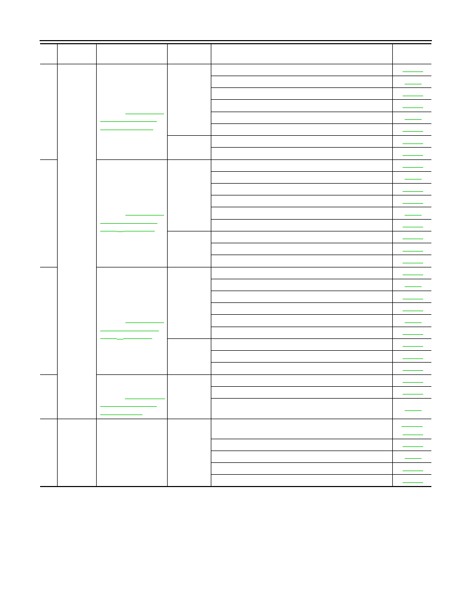
Slips/Will
Not En-
gage
hicle Does Not Creep
Backward in "R" Posi-
tion"
Does Not Creep For-
ward in "D" Position"
ON vehicle
1. A/T fluid level and state
2. Line pressure test
3. Accelerator pedal position sensor
4. Direct clutch solenoid valve
5. PNP switch
6. CAN communication line
7. A/T position
8. Control valve with TCM
OFF vehicle
9. Torque converter
10. Oil pump assembly
11. 1st one-way clutch
12. Gear system
13. Reverse brake
14. Direct clutch
15. Forward one-way clutch (Parts behind drum support is im-
possible to perform inspection by disassembly. Refer to
16, "Cross-Sectional View (2WD Models)"
Sectional View (VQ35DE Models for AWD)"
Sectional View (VK45DE Models for AWD)"
)
16. Forward brake (Parts behind drum support is impossible
to perform inspection by disassembly. Refer to
44
Vehicle cannot run in
all positions.
ON vehicle
1. A/T fluid level and state
2. Line pressure test
3. PNP switch
4. A/T position
5. Control valve with TCM
OFF vehicle
6. Oil pump assembly
7. Gear system
8. Output shaft
No.
Items
Symptom
Condition
Diagnostic Item
Reference
page

TROUBLE DIAGNOSIS
AT-77
< SERVICE INFORMATION >
D
E
F
G
H
I
J
K
L
M
A
B
AT
N
O
P
45
Slips/Will
Not En-
gage
With selector lever in
“D” position, driving is
not possible.
ON vehicle
1. A/T fluid level and state
2. Line pressure test
3. PNP switch
4. A/T position
5. Control valve with TCM
OFF vehicle
6. Torque converter
7. Oil pump assembly
8. 1st one-way clutch
9. Gear system
10. Reverse brake
11. Forward one-way clutch (Parts behind drum support is im-
possible to perform inspection by disassembly. Refer to
16, "Cross-Sectional View (2WD Models)"
Sectional View (VQ35DE Models for AWD)"
Sectional View (VK45DE Models for AWD)"
12. Forward brake (Parts behind drum support is impossible
to perform inspection by disassembly. Refer to
)
46
With selector lever in
“R” position, driving is
not possible.
ON vehicle
1. A/T fluid level and state
2. Line pressure test
3. PNP switch
4. A/T position
5. Control valve with TCM
OFF vehicle
6. Gear system
7. Output shaft
8. Reverse brake
47
Does Not
Change
Does not change M5
→
M4.
Refer to
ON vehicle
1. PNP switch
2. A/T fluid level and state
3. A/T position
4. Manual mode switch
5. CAN communication line
6. Control valve with TCM
OFF vehicle
7. Front brake (brake band)
No.
Items
Symptom
Condition
Diagnostic Item
Reference
page
AT-78
< SERVICE INFORMATION >
TROUBLE DIAGNOSIS
48
Does Not
Change
Does not change M4
→
M3.
ON vehicle
1. PNP switch
2. A/T fluid level and state
3. A/T position
4. Manual mode switch
5. CAN communication line
6. Control valve with TCM
OFF vehicle
7. Front brake (brake band)
8. Input clutch
49
Does not change M3
→
M2.
ON vehicle
1. PNP switch
2. A/T fluid level and state
3. A/T position
4. Manual mode switch
5. CAN communication line
6. Control valve with TCM
OFF vehicle
7. Front brake (brake band)
8. Input clutch
9. High and low reverse clutch
50
Does not change M2
→
M1.
.
ON vehicle
1. PNP switch
2. A/T fluid level and state
3. A/T position
4. Manual mode switch
5. CAN communication line
6. Control valve with TCM
OFF vehicle
7. Input clutch
8. High and low reverse clutch
9. Direct clutch
51
Cannot be changed to
manual mode.
Refer to
not Be Changed to
Manual Mode"
ON vehicle
1. Manual mode switch
2. Turbine revolution sensor
3. CAN communication line
52
Others
Shift point is high in
“D” position.
ON vehicle
1. Vehicle speed sensor A/T and vehicle speed sensor MTR
2. Accelerator pedal position sensor
3. CAN communication line
4. ATF temperature sensor
5. Control valve with TCM
No.
Items
Symptom
Condition
Diagnostic Item
Reference
page

TROUBLE DIAGNOSIS
AT-79
< SERVICE INFORMATION >
D
E
F
G
H
I
J
K
L
M
A
B
AT
N
O
P
53
Others
Shift point is low in “D”
position.
ON vehicle
1. Vehicle speed sensor A/T and vehicle speed sensor MTR
2. Accelerator pedal position sensor
3. CAN communication line
4. Control valve with TCM
54
Judder occurs during
lock-up.
ON vehicle
1. A/T fluid level and state
2. Engine speed signal
3. Turbine revolution sensor
4. Vehicle speed sensor A/T and vehicle speed sensor MTR
5. Accelerator pedal position sensor
6. CAN communication line
7. Torque converter clutch solenoid valve
8. Control valve with TCM
OFF vehicle
9. Torque converter
55
Strange noise in “R”
position.
ON vehicle
1. A/T fluid level and state
2. Engine speed signal
3. CAN communication line
4. Control valve with TCM
OFF vehicle
5. Torque converter
6. Oil pump assembly
7. Gear system
8. High and low reverse clutch
9. Reverse brake
56
Strange noise in “N”
position.
ON vehicle
1. A/T fluid level and state
2. Engine speed signal
3. CAN communication line
4. Control valve with TCM
OFF vehicle
5. Torque converter
6. Oil pump assembly
7. Gear system
No.
Items
Symptom
Condition
Diagnostic Item
Reference
page
Нет комментариевНе стесняйтесь поделиться с нами вашим ценным мнением.
Текст