Infiniti FX35 / FX45. Manual — part 38

AT-80
< SERVICE INFORMATION >
TROUBLE DIAGNOSIS
57
Others
Strange noise in “D”
position.
ON vehicle
1. A/T fluid level and state
2. Engine speed signal
3. CAN communication line
4. Control valve with TCM
OFF vehicle
5. Torque converter
6. Oil pump assembly
7. Gear system
8. Forward brake (Parts behind drum support is impossible to
perform inspection by disassembly. Refer to
58
Vehicle does not de-
celerate by engine
brake.
Refer to
hicle Does Not Decel-
erate by Engine
Brake"
.
ON vehicle
1. PNP switch
2. A/T fluid level and state
3. A/T position
4. Manual mode switch
5. CAN communication line
6. Control valve with TCM
OFF vehicle
7. Input clutch
8. High and low reverse clutch
9. Direct clutch
59
Engine brake does not
work M5
→
M4.
ON vehicle
1. PNP switch
2. A/T fluid level and state
3. A/T position
4. Manual mode switch
5. CAN communication line
6. Control valve with TCM
OFF vehicle
7. Front brake (brake band)
60
Engine brake does not
work M4
→
M3.
ON vehicle
1. PNP switch
2. A/T fluid level and state
3. A/T position
4. Manual mode switch
5. CAN communication line
6. Control valve with TCM
OFF vehicle
7. Front brake (brake band)
8. Input clutch
No.
Items
Symptom
Condition
Diagnostic Item
Reference
page

TROUBLE DIAGNOSIS
AT-81
< SERVICE INFORMATION >
D
E
F
G
H
I
J
K
L
M
A
B
AT
N
O
P
61
Others
Engine brake does not
work M3
→
M2.
ON vehicle
1. PNP switch
2. A/T fluid level and state
3. A/T position
4. Manual mode switch
5. CAN communication line
6. Control valve with TCM
OFF vehicle
7. Front brake (brake band)
8. Input clutch
9. High and low reverse clutch
62
Engine brake does not
work M2
→
M1.
ON vehicle
1. PNP switch
2. A/T fluid level and state
3. A/T position
4. Manual mode switch
5. CAN communication line
6. Control valve with TCM
OFF vehicle
7. Input clutch
8. High and low reverse clutch
9. Direct clutch
63
Maximum speed low.
ON vehicle
1. A/T fluid level and state
2. Line pressure test
3. Accelerator pedal position sensor
4. CAN communication line
5. Direct clutch solenoid valve
6. Control valve with TCM
OFF vehicle
7. Torque converter
8. Oil pump assembly
9. Input clutch
10. Gear system
11. High and low reverse clutch
12. Direct clutch
13. Forward one-way clutch (Parts behind drum support is im-
possible to perform inspection by disassembly. Refer to
16, "Cross-Sectional View (2WD Models)"
Sectional View (VQ35DE Models for AWD)"
Sectional View (VK45DE Models for AWD)"
14. Forward brake (Parts behind drum support is impossible
to perform inspection by disassembly. Refer to
)
No.
Items
Symptom
Condition
Diagnostic Item
Reference
page

AT-82
< SERVICE INFORMATION >
TROUBLE DIAGNOSIS
64
Others
Extremely large creep.
ON vehicle
1. Engine idle speed
VQ35DE)
(for
VK45DE)
2. CAN communication line
OFF vehicle
3. Torque converter
65
With selector lever in
“P” position, vehicle
does not enter parking
condition or, with se-
lector lever in another
position, parking con-
dition is not cancelled.
Refer to
"P" Position, Vehicle
Moves When
Pushed"
.
ON vehicle
1. PNP switch
2. A/T position
OFF vehicle
3. Parking pawl components
models) or
(AWD
models)
66
Vehicle runs with A/T
in “P” position.
ON vehicle
1. PNP switch
2. A/T fluid level and state
3. A/T position
4. Control valve with TCM
OFF vehicle
5. Parking pawl components
models) or
(AWD
models)
6. Gear system
67
Vehicle runs with A/T
in “N” position.
Refer to
.
ON vehicle
1. PNP switch
2. A/T fluid level and state
3. A/T position
4. Control valve with TCM
OFF vehicle
5. Input clutch
6. Gear system
7. Direct clutch
8. Reverse brake
9. Forward one-way clutch (Parts behind drum support is im-
possible to perform inspection by disassembly. Refer to
16, "Cross-Sectional View (2WD Models)"
Sectional View (VQ35DE Models for AWD)"
Sectional View (VK45DE Models for AWD)"
)
10. Low coast brake (Parts behind drum support is impossible
to perform inspection by disassembly. Refer to
No.
Items
Symptom
Condition
Diagnostic Item
Reference
page
TROUBLE DIAGNOSIS
AT-83
< SERVICE INFORMATION >
D
E
F
G
H
I
J
K
L
M
A
B
AT
N
O
P
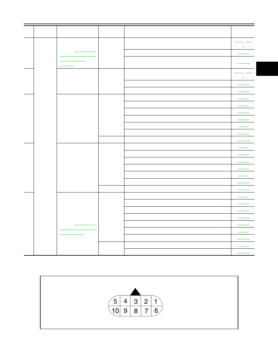
TCM Input/Output Signal Reference Value
INFOID:0000000001327162
A/T ASSEMBLY HARNESS CONNECTOR TERMINAL LAYOUT
TCM INSPECTION TABLE
68
Others
Engine does not start
in “N” or “P” position.
Refer to
gine Cannot Be Start-
ed in "P" or "N"
Position"
ON vehicle
1. Ignition switch and starter
2. A/T position
3. PNP switch
69
Engine starts in posi-
tions other than “N” or
“P”.
ON vehicle
1. Ignition switch and starter
2. A/T position
3. PNP switch
70
Engine stall.
ON vehicle
1. A/T fluid level and state
2. Engine speed signal
3. Turbine revolution sensor
4. Torque converter clutch solenoid valve
5. CAN communication line
6. Control valve with TCM
OFF vehicle
7. Torque converter
71
Engine stalls when se-
lector lever shifted “N”
→
“D”, “R”.
ON vehicle
1. A/T fluid level and state
2. Engine speed signal
3. Turbine revolution sensor
4. Torque converter clutch solenoid valve
5. CAN communication line
6. Control valve with TCM
OFF vehicle
7. Torque converter
72
Engine speed does
not return to idle.
Refer to
gine Speed Does Not
Return to Idle"
ON vehicle
1. A/T fluid level and state
2. Direct clutch solenoid valve
3. Front brake solenoid valve
4. Accelerator pedal position sensor
5. Vehicle speed sensor A/T and vehicle speed sensor MTR
6. CAN communication line
7. Control valve with TCM
OFF vehicle
8. Front brake (brake band)
9. Direct clutch
No.
Items
Symptom
Condition
Diagnostic Item
Reference
page
SCIA1658E
Нет комментариевНе стесняйтесь поделиться с нами вашим ценным мнением.
Текст