Infiniti FX35 / FX45. Manual — part 332
TROUBLE DIAGNOSIS
EC-89
< SERVICE INFORMATION >
[VQ35DE]
C
D
E
F
G
H
I
J
K
L
M
A
EC
N
P
O
TROUBLE DIAGNOSIS
Trouble Diagnosis Introduction
INFOID:0000000001325927
INTRODUCTION
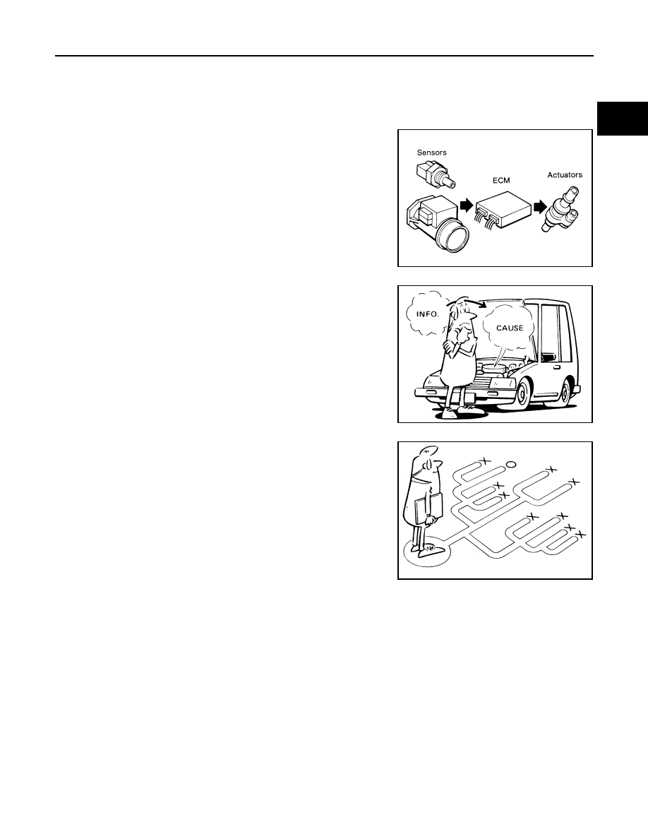
The engine has an ECM to control major systems such as fuel con-
trol, ignition control, idle air control system, etc. The ECM accepts
input signals from sensors and instantly drives actuators. It is essen-
tial that both input and output signals are proper and stable. At the
same time, it is important that there are no malfunctions such as vac-
uum leaks, fouled spark plugs, or other malfunctions with the engine.
It is much more difficult to diagnose an incident that occurs intermit-
tently rather than continuously. Most intermittent incidents are
caused by poor electric connections or improper wiring. In this case,
careful checking of suspected circuits may help prevent the replace-
ment of good parts.
A visual check only may not find the cause of the incidents. A road
test with CONSULT-III (or GST) or a circuit tester connected should
be performed. Follow the WORK FLOW on “WORK FLOW”.
Before undertaking actual checks, take a few minutes to talk with a
customer who approaches with a driveability complaint. The cus-
tomer can supply good information about such incidents, especially
intermittent ones. Find out what symptoms are present and under
what conditions they occur. A DIAGNOSTIC WORKSHEET like the
example on “DIAGNOSTIC WORKSHEET” should be used.
Start your diagnosis by looking for conventional malfunctions first.
This will help troubleshoot driveability malfunctions on an electroni-
cally controlled engine vehicle.
WORK FLOW
MEF036D
SEF233G
SEF234G
EC-90
< SERVICE INFORMATION >
[VQ35DE]
TROUBLE DIAGNOSIS
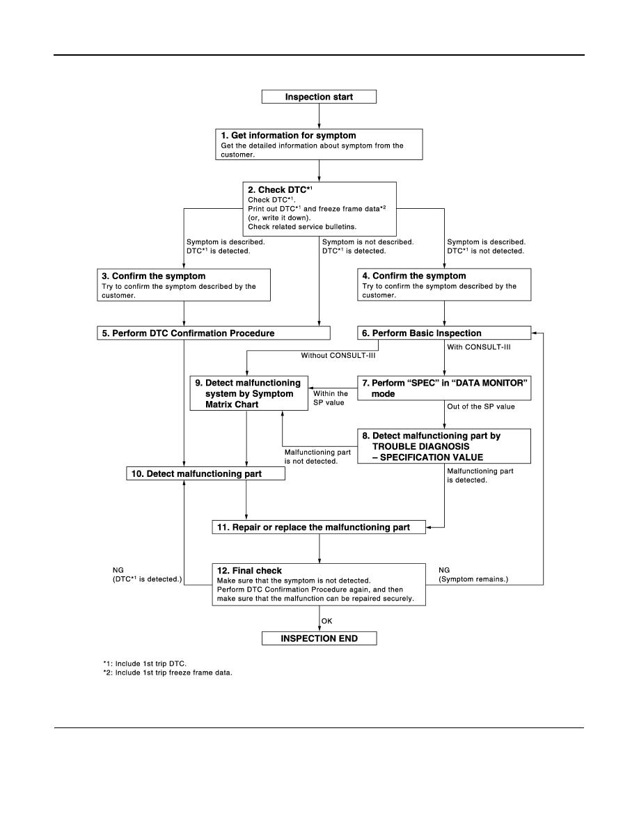
Overall Sequence
Detailed Flow
1.
GET INFORMATION FOR SYMPTOM
Get the detailed information from the customer about the symptom (the condition and the environment when
the incident/malfunction occurred) using the “DIAGNOSTIC WORKSHEET”.
>> GO TO 2.
PBIB3637E

TROUBLE DIAGNOSIS
EC-91
< SERVICE INFORMATION >
[VQ35DE]
C
D
E
F
G
H
I
J
K
L
M
A
EC
N
P
O
2.
CHECK DTC*
1
1.
Check DTC*
1
.
2.
Perform the following procedure if DTC*
1
is displayed.
-
Record DTC*
1
and freeze frame data*
2
. (Print them out with CONSULT-III or GST.)
-
Erase DTC*
1
. (Refer to
EC-55, "Emission-Related Diagnostic Information"
-
Study the relationship between the cause detected by DTC*
1
and the symptom described by the cus-
tomer. (Symptom Matrix Chart is useful. Refer to
3.
Check related service bulletins for information.
Is any symptom described and any DTC detected?
Symptom is described, DTC*
1
is displayed>>GO TO 3.
Symptom is described, DTC*
1
is not displayed>>GO TO 4.
Symptom is not described, DTC*
1
is displayed>>GO TO 5.
3.
CONFIRM THE SYMPTOM
Try to confirm the symptom described by the customer (except MIL ON).
DIAGNOSIS WORK SHEET is useful to verify the incident.
Connect CONSULT-III to the vehicle and check diagnosis results.
Verify relation between the symptom and the condition when the symptom is detected.
>> GO TO 5.
4.
CONFIRM THE SYMPTOM
Try to confirm the symptom described by the customer.
DIAGNOSIS WORK SHEET is useful to verify the incident.
Connect CONSULT-III to the vehicle and check diagnosis results.
Verify relation between the symptom and the condition when the symptom is detected.
>> GO TO 6.
5.
PERFORM DTC CONFIRMATION PROCEDURE
Perform DTC Confirmation Procedure for the displayed DTC*
1
, and then make sure that DTC*
1
is detected
again.
If two or more DTCs*
1
are detected, refer to
EC-93, "DTC Inspection Priority Chart"
diagnosis order.
NOTE:
• Freeze frame data*
2
is useful if the DTC*
1
is not detected.
• Perform Overall Function Check if DTC Confirmation Procedure is not included on Service Manual. This
simplified check procedure is an effective alternative though DTC*
1
cannot be detected during this check.
If the result of Overall Function Check is NG, it is the same as the detection of DTC*
1
by DTC Confirmation
Procedure.
Is DTC*
1
detected?
Yes
>> GO TO 10.
No
>> Check according to
.
6.
PERFORM BASIC INSPECTION
Perform
With CONSULT-III>>GO TO 7.
Without CONSULT-III>>GO TO 9.
7.
PERFORM SPEC IN DATA MONITOR MODE
With CONSULT-III
Make sure that “MAS A/F SE-B1”, “B/FUEL SCHDL”, and “A/F ALPHA-B1”, “A/F ALPHA-B2” are within the SP
value using CONSULT-III “SPEC” in “DATA MONITOR” mode. Refer to
.

EC-92
< SERVICE INFORMATION >
[VQ35DE]
TROUBLE DIAGNOSIS
Are they within the SP value?
Yes
>> GO TO 9.
No
>> GO TO 8.
8.
DETECT MALFUNCTIONING PART BY TROUBLE DIAGNOSIS - SPECIFICATION VALUE
Detect malfunctioning part according to
Is malfunctioning part detected?
Yes
>> GO TO 11.
No
>> GO TO 9.
9.
DETECT MALFUNCTIONING SYSTEM BY SYMPTOM MATRIX CHART
Detect malfunctioning system according to
based on the confirmed symptom
in step 4, and determine the trouble diagnosis order based on possible causes and symptom.
>> GO TO 10.
10.
DETECT MALFUNCTIONING PART BY DIAGNOSTIC PROCEDURE
Inspect according to Diagnostic Procedure of the system.
NOTE:
The Diagnostic Procedure in EC section described based on open circuit inspection. A short circuit inspection
is also required for the circuit check in the Diagnostic Procedure. For details, refer to Circuit Inspection in
25, "How to Perform Efficient Diagnosis for an Electrical Incident"
Is malfunctioning part detected?
Yes
>> GO TO 11.
No
>> Monitor input data from related sensors or check voltage of related ECM terminals using CON-
EC-127, "CONSULT-III Reference Value in Data Monitor Mode"
11.
REPAIR OR REPLACE THE MALFUNCTIONING PART
1.
Repair or replace the malfunctioning part.
2.
Reconnect parts or connectors disconnected during Diagnostic Procedure again after repair and replace-
ment.
3.
Check DTC. If DTC is displayed, erase it, refer to
EC-55, "Emission-Related Diagnostic Information"
>> GO TO 12.
12.
FINAL CHECK
When DTC was detected in step 2, perform DTC Confirmation Procedure or Overall Function Check again,
and then make sure that the malfunction have been repaired securely.
When symptom was described from the customer, refer to confirmed symptom in step 3 or 4, and make sure
that the symptom is not detected.
OK or NG
NG (DTC*
1
is detected)>>GO TO 10.
NG (Symptom remains)>>GO TO 6.
OK
>> 1.
Before returning the vehicle to the customer, make sure to erase unnecessary DTC*
1
in ECM
and TCM (Transmission Control Module). (Refer to
EC-55, "Emission-Related Diagnostic
AT-38, "OBD-II Diagnostic Trouble Code (DTC)"
.)
2.
If the completion of SRT is needed, drive vehicle under the specific driving pattern. Refer to
EC-55, "Emission-Related Diagnostic Information"
3.
INSPECTION END
*1: Include 1st trip DTC.
*2: Include 1st trip freeze frame data.
DIAGNOSTIC WORKSHEET
Description
Нет комментариевНе стесняйтесь поделиться с нами вашим ценным мнением.
Текст