Infiniti FX35 / FX45. Manual — part 149

AV-50
< SERVICE INFORMATION >
ANTENNA
1.
Attach probe circuit tester (ohm setting) to antenna terminal on
each side.
• When measuring continuity, wrap tin foil around the top of
probe. Then, press the foil against the wire with your fin-
ger.
2.
If an element is broken, no continuity will exist.
3.
To locate a break, move probe along element. Tester needle will
swing abruptly when probe passes the broken point.
SEL250I
SEL122R
SEL252I
SEL253I

ANTENNA
AV-51
< SERVICE INFORMATION >
C
D
E
F
G
H
I
J
L
M
A
B
AV
N
O
P
Removal and Installation of Roof Antenna
INFOID:0000000001328708
REMOVAL
1.
Remove head lining. Refer to
.
2.
Remove nut and remove rod and antenna base.
3.
Remove instrument panel. Refer to
.
4.
Disassembly antenna feeder (upper) and antenna feeder
(lower).
5.
Disengaged the clips (7) to separate antenna feeder (upper)
from vehicle.
6.
Pull off antenna feeder (lower) from audio unit.
7.
Disengaged the clips (5) to separate antenna feeder (lower)
from vehicle.
INSTALLATION
Installation is the reverse order of removal.
Removal and Installation of Satellite Radio Antenna
INFOID:0000000001328709
AV-45, "Removal and Installation of Satellite Radio Antenna"
.
PKIA2463E
SKIA5821E
AV-52
< SERVICE INFORMATION >
INTEGRATED DISPLAY SYSTEM
INTEGRATED DISPLAY SYSTEM
System Description
INFOID:0000000001328710
For system operation information, refer to Owner's Manual.
INTEGRATED DISPLAY SYSTEM
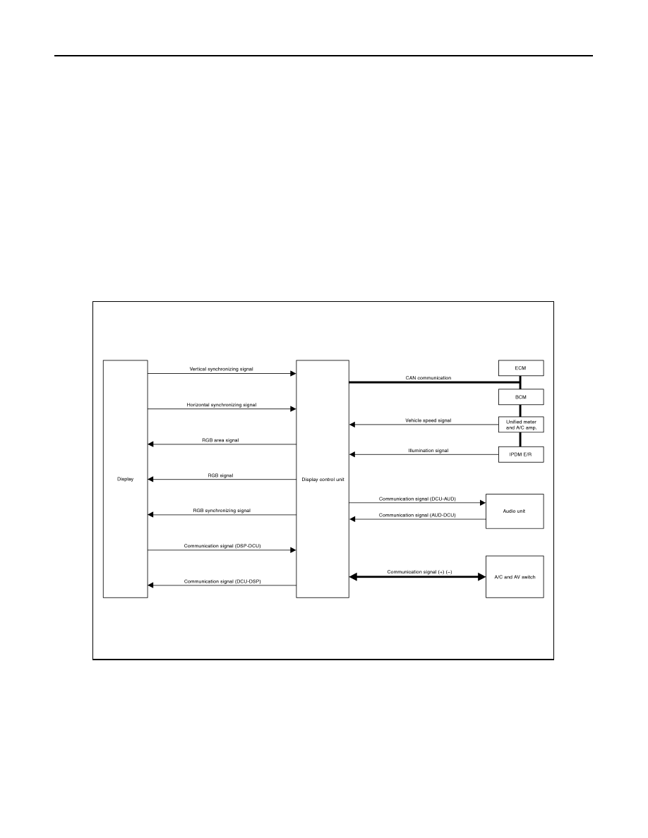
• Each control unit that comprises the system is connected with a communication circuit. It transmits/receives
data signals including request signals and response signals, and controls the system.
• The display control unit transmits/receives data signals to/from each control unit with CAN communication. It
performs an arithmetical operation on fuel information values by using data obtained from the control units,
and then displays the calculated values on the screen.
• The display control unit receives door switch signals from the BCM with CAN communication, and displays a
warning on the screen when driving over the set speed with a door half-shut.
• The display control unit receives vehicle speed signals that are transmitted from the unified meter and A/C
amp., performs an arithmetical operation on drive information values, and then displays the calculated val-
ues on the screen.
• The images displayed on the monitor screen contain display control unit-generated RGB images.
• The display control unit controls image switching and image quality adjustments by communications with the
display.
Component Description
INFOID:0000000001328711
DISPLAY CONTROL UNIT
SKIB8651E
INTEGRATED DISPLAY SYSTEM
AV-53
< SERVICE INFORMATION >
C
D
E
F
G
H
I
J
L
M
A
B
AV
N
O
P
• Display control unit draws a status of the audio and air conditioner,
a TRIP screen, a FUEL ECONOMY screen, etc., and transmits the
image signals to the display screen.
• It receives operation signals of audio and air conditioner from A/C
and AV switch, and transmits the operation signal of audio to the
audio unit via the communication line and transmits the operation
signal of air conditioner to the meter and A/C amp. via CAN com-
munication.
DISPLAY
• Images on the display include RGB image such as map screen.
• Display control unit controls images on the display.
A/C AND AV SWITCH
• A/C and AV switch, an integrated combination of audio and air con-
ditioner switches, are adopted.
• Operation signal of audio is transmitted to the audio unit through
display control unit with the communication line. Operation signal
of air conditioner is transmitted to meter and A/C amp. through dis-
play control unit with CAN communication.
CAN Communication Unit
INFOID:0000000001328712
LAN-43, "CAN System Specification Chart"
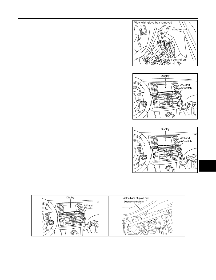
Component Parts Location
INFOID:0000000001328713
SKIB8638E
SKIB8639E
SKIB8639E
SKIB8645E
Нет комментариевНе стесняйтесь поделиться с нами вашим ценным мнением.
Текст