Infiniti FX35 / FX45. Manual — part 897
RSU-4
< SERVICE INFORMATION >
NOISE, VIBRATION AND HARSHNESS (NVH) TROUBLESHOOTING
NOISE, VIBRATION AND HARSHNESS (NVH) TROUBLESHOOTING
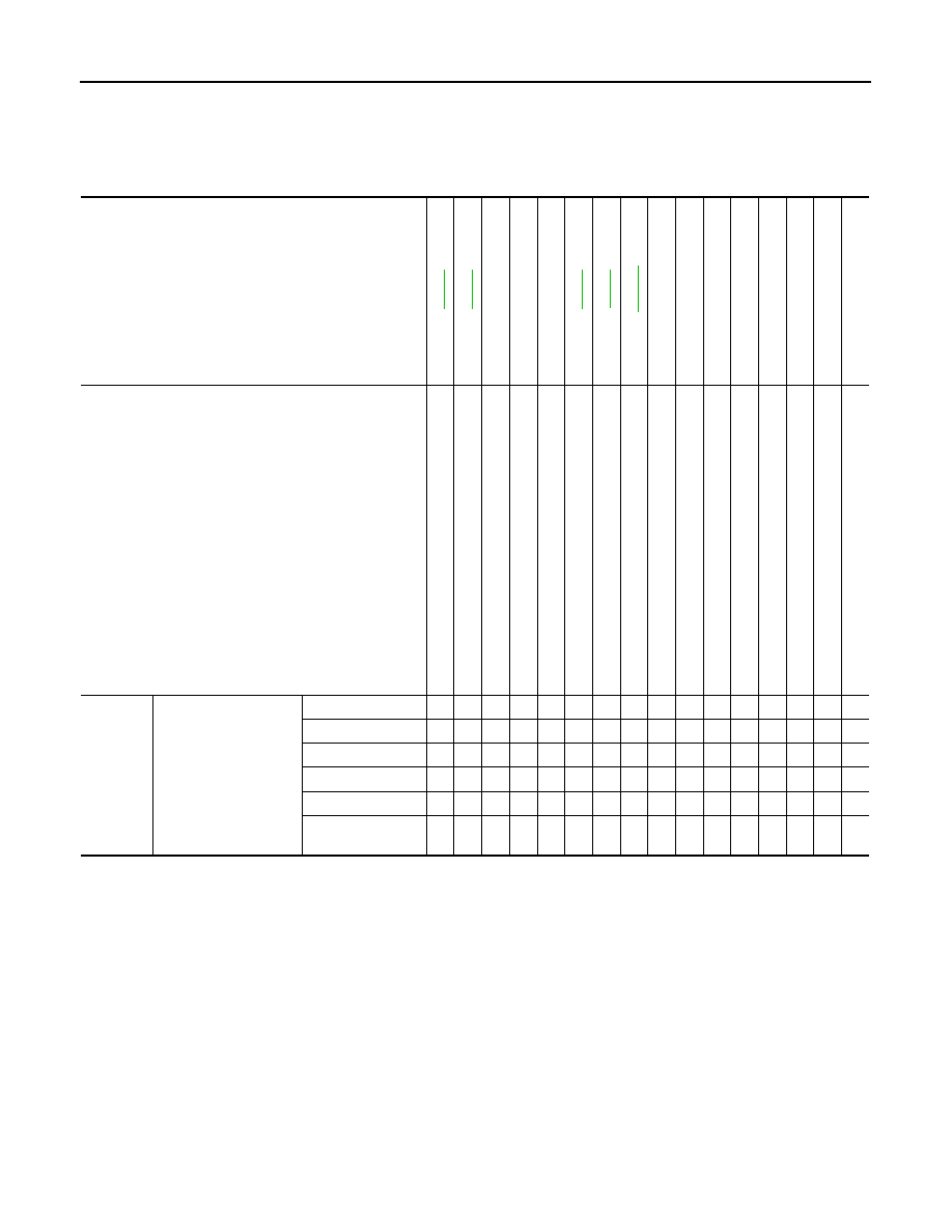
NVH Troubleshooting Chart
INFOID:0000000001327551
Use chart below to help you find the cause of the symptom. If necessary, repair or replace these parts.
×
: Applicable
Reference page
—
—
—
NVH in PR
section
NVH in RFD
section
NVH in RAX
and RSU
section
NVH in WT
section
NVH in WT
section
NVH in RAX
section
NVH in BR
section
NVH in PS
section
Possible cause and SUSPECTED PARTS
Imp
rop
er i
ns
ta
lla
ti
o
n,
lo
os
en
es
s
Sh
oc
k
ab
so
rbe
r de
form
a
tio
n,
dam
a
g
e
or d
e
flec
ti
on
Bu
sh
in
g o
r m
o
u
n
ti
ng
de
teri
ora
tio
n
Part
s interf
erence
S
p
rin
g
f
a
ti
gu
e
Su
sp
en
si
on
lo
os
en
es
s
In
co
rrec
t wh
ee
l a
lig
nm
en
t
S
tab
ili
ze
r ba
r fa
tig
u
e
PROPELLER S
H
AFT
DIFF
ERENTIAL
REAR A
X
LE
AND REAR SUSP
ENSION
TI
RE
ROAD
WHEEL
DRIVE SHAFT
BRAKE
STE
E
RING
Symptom
REAR SUSPENSION
Noise
×
×
×
×
×
×
×
×
×
×
×
×
×
×
Shake
×
×
×
×
×
×
×
×
×
×
×
×
Vibration
×
×
×
×
×
×
×
×
×
×
Shimmy
×
×
×
×
×
×
×
×
×
×
Judder
×
×
×
×
×
×
×
×
Poor quality ride or
handling
×
×
×
×
×
×
×
×
×
×
REAR SUSPENSION ASSEMBLY
RSU-5
< SERVICE INFORMATION >
C
D
F
G
H
I
J
K
L
M
A
B
RSU
N
O
P
REAR SUSPENSION ASSEMBLY
On-Vehicle Inspection and Service
INFOID:0000000001327552
Make sure the mounting conditions (looseness, back lash) of each component and component status (wear,
damage) are normal.
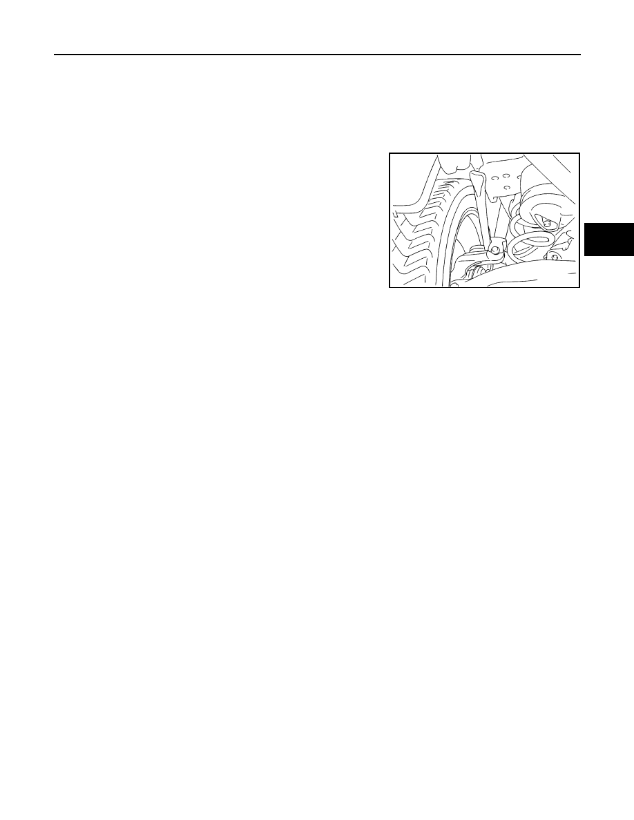
INSPECTION OF BALL JOINT END PLAY
Measure axial end play by installing and moving up/down with an
iron pry bar or something similar between suspension arm and axle.
CAUTION:
Be careful not to damage ball joint boot.
SHOCK ABSORBER INSPECTION
Check shock absorber for oil leakage, damage and replace if necessary.
Wheel AlignmentInspection
INFOID:0000000001327553
DESCRIPTION
• Measure wheel alignment under unladen conditions. “Unladen conditions” means that fuel, engine coolant,
and lubricant are full. Spare tire, jack, hand tools and mats in designated positions.
PRELIMINARY INSPECTION
• Check tires for improper air pressure and wear.
• Check road wheels for runout.
• Check wheel bearing axial end play.
• Check ball joint axial end play of suspension arm.
• Check shock absorber operation.
• Check each mounting point of axle and suspension for looseness and deformation.
• Check each link, arm and member for cracks, deformation, and other damage.
• Check vehicle posture.
GENERAL INFORMATION AND RECOMMENDATIONS
• A four-wheel thrust alignment should be performed.
- This type of alignment is recommended for any NISSAN/INFINITI vehicle.
- The four-wheel “thrust” process helps ensure that the vehicle is properly aligned and the steering wheel is
centered.
- The alignment rack itself should be capable of accepting any NISSAN/INFINITI vehicle.
- The rack should be checked to ensure that it is level.
• Make sure the machine is properly calibrated.
- Your alignment equipment should be regularly calibrated in order to give correct information.
- Check with the manufacturer of your specific equipment for their recommended Service/Calibration Sched-
ule.
THE ALIGNMENT PROCESS
IMPORTANT:
Use only the alignment specifications listed in this Service Manual.
• When displaying the alignment settings, many alignment machines use “indicators”: (Green/red, plus or
minus, Go/No Go). Do NOT use these indicators.
- The alignment specifications programmed into your machine that operate these indicators may not be cor-
rect.
- This may result in an ERROR.
• Some newer alignment machines are equipped with an optional “Rolling Compensation” method to “com-
pensate” the sensors (alignment targets or head units). DO NOT use this “Rolling Compensation”
method.
Standard value
Axial end play
: 0 mm (0 in)
SEIA0245J
RSU-6
< SERVICE INFORMATION >
REAR SUSPENSION ASSEMBLY
- Use the “Jacking Compensation Method”. After installing the alignment targets or head units, raise the vehi-
cle and rotate the wheels 1/2 turn both ways.
- See Instructions in the alignment machine you're using for more information on this.
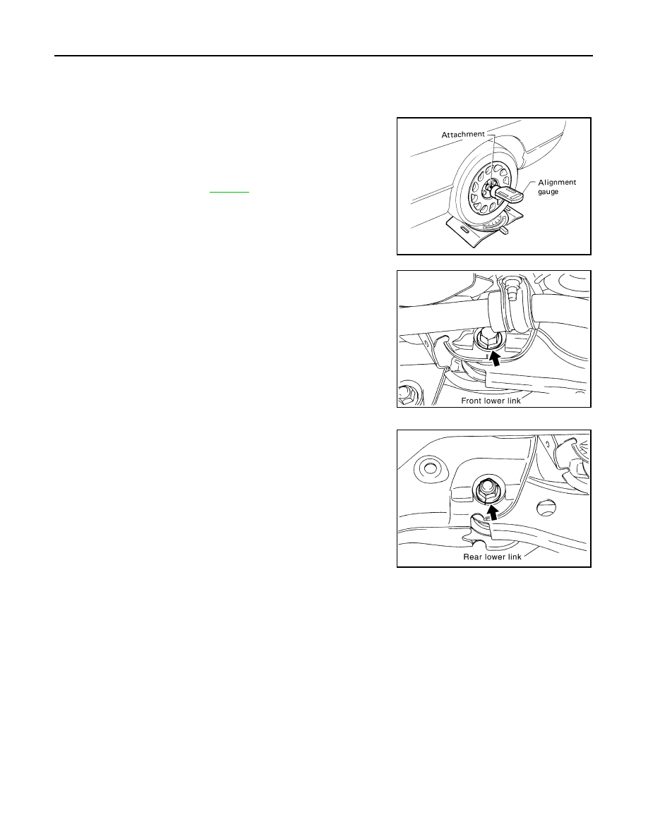
CAMBER INSPECTION
• Measure camber of both right and left wheels with a suitable align-
ment gauge and adjust in accordance with the following proce-
dures.
If outside the standard value, adjust with adjusting bolt in front
lower link.
NOTE:
After adjusting camber, be sure to check toe-in.
TOE-IN
If toe-in is not within the specification, adjust with adjusting bolt in
rear lower link.
CAUTION:
Be sure to adjust equally on RH and LH side with adjusting bolt.
If toe-in is not still within the specification, inspect and replace any
damaged or worn rear suspension parts.
Removal and Installation
INFOID:0000000001327554
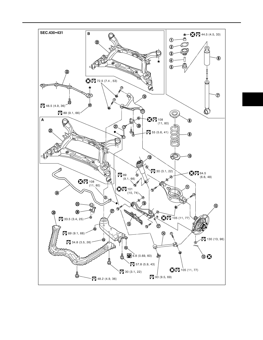
COMPONENTS
Standard value
Camber
.
SRA096A
SEIA0318E
SEIA0319E
REAR SUSPENSION ASSEMBLY
RSU-7
< SERVICE INFORMATION >
C
D
F
G
H
I
J
K
L
M
A
B
RSU
N
O
P
1.
Bushing
2.
Mounting seal
3.
Mounting seal bracket
4.
Distance tube
5.
Bound bumper cover
6.
Bound bumper
7.
Shock absorber
8.
Upper seat
9.
Coil spring
10. Rubber seat
11. Rear lower link
12. Axle assembly
13. Cotter pin
14. Radius rod
15. Front lower link protector
16. Front lower link
17. Stopper rubber
18. Shock absorber assembly
JPEIB0031GB
Нет комментариевНе стесняйтесь поделиться с нами вашим ценным мнением.
Текст