Infiniti FX35 / FX45. Manual — part 898

RSU-8
< SERVICE INFORMATION >
REAR SUSPENSION ASSEMBLY
REMOVAL
1.
Remove tires from vehicle with power tool.
2.
Remove brake caliper with power tool. Hang it in a place where it will not interfere with work. Refer to
.
NOTE:
Avoid depressing brake pedal while brake caliper is removed.
3.
Remove wheel sensor from rear final drive, then remove wheel sensor harness from rear suspension
member.
4.
Remove height sensor harness from rear suspension member (if equipped).
5.
Remove center muffler and main muffler. Refer to
6.
Remove stabilizer bar. Refer to
RSU-16, "Removal and Installation"
7.
Remove rear propeller shaft. Refer to
PR-9, "Removal and Installation"
8.
Separate attachments between parking brake cable and vehicle and rear suspension member.
9.
Remove rear lower link and coil spring. Refer to
RSU-14, "Removal and Installation"
.
10. Remove fixing bolt in lower side of shock absorber with power tool.
11. Set jack under rear final drive.
12. Remove fixing bolts and nuts of tunnel stay and member stay with power tool, then remove those parts
from vehicle.
13. Remove fixing bolts and nuts of rear pin stay with power tool and then remove rear pin stay from vehicle.
14. Gradually lowering jack, remove rear suspension assembly.
INSTALLATION
• Refer to "Removal and installation" for tightening torque. Install in the reverse order of removal.
NOTE:
Refer to component parts location and do not reuse non-reusable parts.
• Perform final tightening of installation position of links (rubber bushing) under unladen conditions with tires
on level ground. Check wheel alignment. Refer to
RSU-5, "Wheel AlignmentInspection"
• After adjusting wheel alignment, adjust neutral position of steering angle sensor. Refer to
ment of Steering Angle Sensor Neutral Position"
19. Suspension arm
20. Stabilizer connecting rod mounting
bracket
21. Stabilizer connecting rod
22. Rear pin stay
23. Rear suspension member
24. Stabilizer bar
25. Stabilizer bushing
26. Stabilizer clamp
27. Member stay
28. Tunnel stay
A:
With height sensor
B:
Without height sensor
Refer to
, for the symbols in the figure.
SHOCK ABSORBER
RSU-9
< SERVICE INFORMATION >
C
D
F
G
H
I
J
K
L
M
A
B
RSU
N
O
P
SHOCK ABSORBER
Removal and Installation
INFOID:0000000001327555
REMOVAL
1.
Remove tires from vehicle with power tool.
2.
Set jack under rear lower link.
3.
Remove fixing bolt in lower side of shock absorber assembly with power tool.
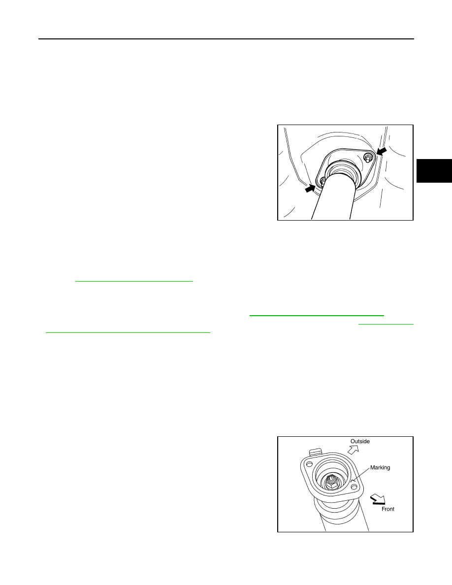
4.
Remove fixing nuts in upper side of shock absorber assembly
with power tool and remove shock absorber assembly from
vehicle.
INSPECTION AFTER REMOVAL
• Check shock absorber assembly for deformation, cracks, or damage, and replace if necessary.
• Check piston rod for damage, uneven wear, or distortion, and replace if necessary.
• Check welded and sealed areas for oil leakage, and replace if necessary.
INSTALLATION
• Refer to
RSU-6, "Removal and Installation"
for tightening torque. Install in the reverse order of removal.
NOTE:
Refer to component parts location and do not reuse non-reusable parts.
• Perform final tightening of shock absorber assembly lower side (rubber bushing) under unladen conditions
with tires on level ground. Check wheel alignment. Refer to
RSU-18, "Wheel Alignment (Unladen*)"
.
• After adjusting wheel alignment, adjust neutral position of steering angle sensor. Refer to
ment of Steering Angle Sensor Neutral Position"
Disassembly and Assembly
INFOID:0000000001327556
DISASSEMBLY
CAUTION:
Make sure piston rod on shock absorber is not damaged when removing components from shock
absorber.
1.
Remove mounting seal from mounting seal bracket.
2.
Wrap a shop cloth around lower side of shock absorber and fix it in a vise.
CAUTION:
Do not set the cylindrical part of shock absorber in vise.
3.
Fix piston rod with hexagon wrench, and remove piston rod lock
nut.
4.
Remove mounting seal bracket, bushing, distance tube, bound
bumper cover and bound bumper from shock absorber.
INSPECTION AFTER DISASSEMBLY
Bound Bumper and Bushing
FA-0274D
SEIA0366E
RSU-10
< SERVICE INFORMATION >
SHOCK ABSORBER
Check bound bumper and bushing for cracks, deformation or other damage. Replace if necessary.
ASSEMBLY
• Refer to
RSU-6, "Removal and Installation"
for tightening torque. Assembly in the reverse order of disas-
sembly.
NOTE:
• Refer to component parts location and do not reuse non-reusable parts.
• Make sure piston rod on shock absorber is not damaged when attaching components to shock absorber.
SUSPENSION ARM
RSU-11
< SERVICE INFORMATION >
C
D
F
G
H
I
J
K
L
M
A
B
RSU
N
O
P
SUSPENSION ARM
Removal and Installation
INFOID:0000000001327557
REMOVAL
1.
Remove tires from vehicle with power tool.
2.
Remove stabilizer connecting rod mounting bracket from suspension arm with power tool.
3.
Remove drive shaft from vehicle. (VK45DE models) Refer to
RAX-10, "Removal and Installation"
.
4.
Remove cotter pin of suspension arm ball joint, and loosen nut.
5.
Use a ball joint remover (suitable tool) to remove suspension arm from axle assembly. Be careful not to
damage ball joint boot.
CAUTION:
Tighten temporarily mounting nut to prevent damage to threads and to prevent ball joint remover
(suitable tool) from coming off.
6.
Remove fixing nuts and bolts between suspension arm and rear suspension member with power tool.
7.
Remove suspension arm from vehicle.
INSPECTION AFTER REMOVAL
Visual Inspection
• Check suspension arm and bushing for deformation, cracks, or damage. If any non-standard condition is
found, replace it.
• Check boot of ball joint for cracks, or damage, and also for grease leakage.
Ball Joint Inspection
Manually move ball stud to confirm it moves smoothly with no binding.
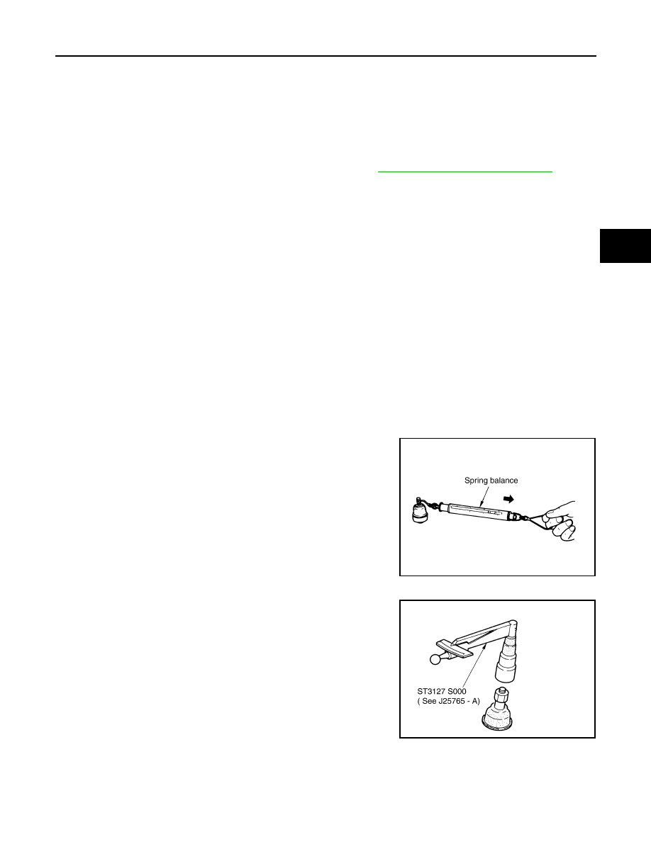
Swing Torque Inspection
NOTE:
Before measuring, move ball joint at least ten times by hand to check for smooth movement.
• Hook a spring balance at cotter pin mounting hole. Confirm spring
balance measurement value is within the specifications when ball
stud begins moving.
• If it is outside the specified range, replace suspension arm assem-
bly.
Rotating Torque Inspection
• Attach mounting nut to ball stud. Make sure rotating torque is
within the specifications with a preload gauge (SST).
• If it is outside the specified range, replace suspension arm assem-
bly.
Axial End Play Inspection
• Move tip of ball joint in axial direction to check for looseness.
Swing torque:
0.5
−
3.4 N·m (0.06
−
0.34 kg-m, 5
−
30 in-lb)
Measured value of spring scale:
9.7
−
66.0 N (0.98
−
6.7 kg, 2.18
−
14.8 lb)
SEIA0523E
Rotating torque:
0.5
−
3.4 N·m (0.06
−
0.34 kg-m, 5 - 30 in-lb)
SDIA1150E
Axial end play
: 0 mm (0 in)
Нет комментариевНе стесняйтесь поделиться с нами вашим ценным мнением.
Текст