Infiniti FX35 / FX45. Manual — part 351
DTC P0037, P0038, P0057, P0058 HO2S2 HEATER
EC-165
< SERVICE INFORMATION >
[VQ35DE]
C
D
E
F
G
H
I
J
K
L
M
A
EC
N
P
O
Diagnosis Procedure
INFOID:0000000001325978
1.
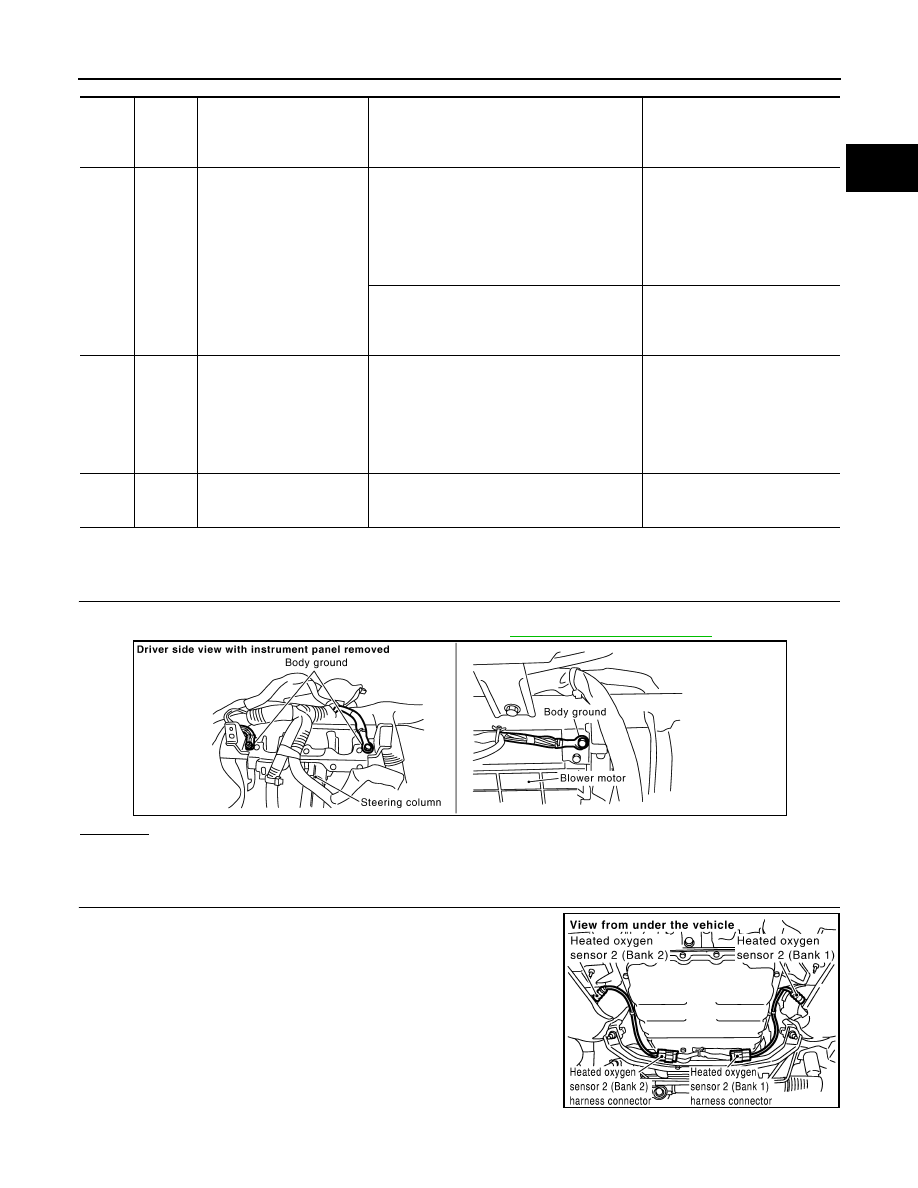
CHECK GROUND CONNECTIONS
1.
Turn ignition switch OFF.
2.
Loosen and retighten ground screw on the body. Refer to
OK or NG
OK
>> GO TO 2.
NG
>> Repair or replace ground connections.
2.
CHECK HO2S2 POWER SUPPLY CIRCUIT
1.
Disconnect heated oxygen sensor 2 harness connector.
2.
Turn ignition switch ON.
TER-
MI-
NAL
NO.
WIRE
COLOR
ITEM
CONDITION
DATA (DC Voltage)
6
R
Heated oxygen sensor 2
heater (bank 2)
[Engine is running]
• Engine speed: Below 3,600 rpm after the fol-
lowing conditions are met.
- Engine: After warming up
- Keeping the engine speed between 3,500
and 4,000 rpm for 1 minute and at idle for 1
minute under no load
0 - 1.0V
[Ignition switch: ON]
• Engine stopped
[Engine is running]
• Engine speed: Above 3,600 rpm
BATTERY VOLTAGE
(11 - 14V)
55
W/R
Heated oxygen sensor 2
(bank 2)
[Engine is running]
• Revving engine from idle to 3,000 rpm quick-
ly after the following conditions are met
- Engine: After warming up
- Keeping the engine speed between 3,500
and 4,000 rpm for 1 minute and at idle for 1
minute under no load
0 - Approximately 1.0V
78
B/R
Sensor ground
(Heated oxygen sensor)
[Engine is running]
• Warm-up condition
• Idle speed
Approximately 0V
PBIB2625E
PBIB1576E
EC-166
< SERVICE INFORMATION >
[VQ35DE]
DTC P0037, P0038, P0057, P0058 HO2S2 HEATER
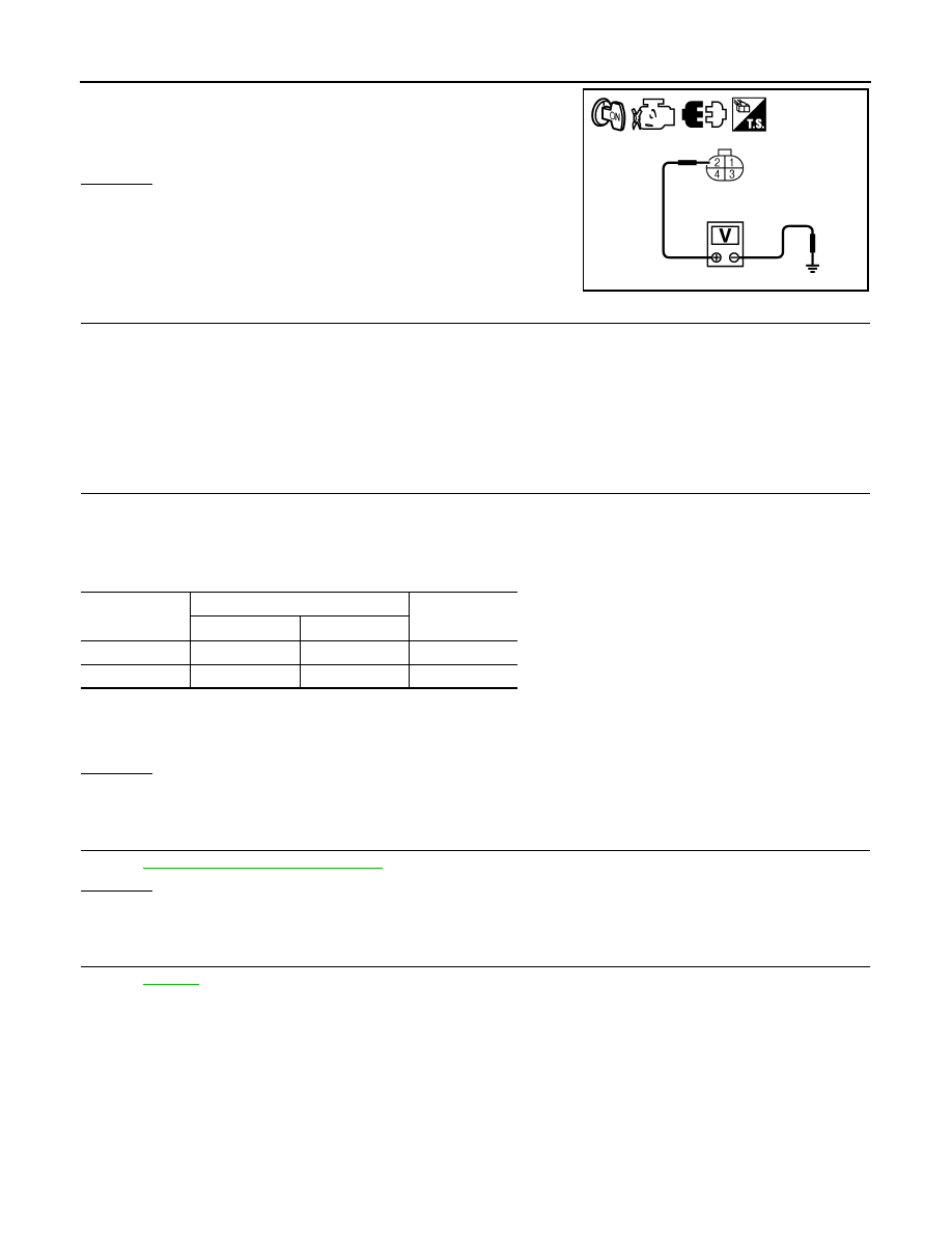
3.
Check voltage between HO2S2 terminal 2 and ground with
CONSULT-III or tester.
OK or NG
OK
>> GO TO 4.
NG
>> GO TO 3.
3.
DETECT MALFUNCTIONING PART
Check the following.
• Harness connectors E64, F65
• IPDM E/R harness connector E7
• 10A fuse
• Harness for open or short between heated oxygen sensor 2 and fuse
>> Repair open circuit or short ground or short to power in harness or connectors.
4.
CHECK HO2S2 HEATER OUTPUT SIGNAL CIRCUIT FOR OPEN AND SHORT
1.
Turn ignition switch OFF.
2.
Disconnect ECM harness connector.
3.
Check harness continuity between ECM terminal and HO2S2 terminal as follows.
Refer to Wiring Diagram.
4.
Also check harness for short to ground and short to power.
OK or NG
OK
>> GO TO 5.
NG
>> Repair open circuit or short to ground or short to power in harness or connectors.
5.
CHECK HEATED OXYGEN SENSOR 2 HEATER
EC-166, "Component Inspection"
OK or NG
OK
>> GO TO 6.
NG
>> Replace malfunctioning heated oxygen sensor 2.
6.
CHECK INTERMITTENT INCIDENT
>> INSPECTION END
Component Inspection
INFOID:0000000001325979
HEATED OXYGEN SENSOR 2 HEATER
Voltage: Battery voltage
PBIA9576J
DTC
Terminals
Bank
ECM
Sensor
P0037, P0038
25
3
1
P0057, P0058
6
3
2
Continuity should exist.
DTC P0037, P0038, P0057, P0058 HO2S2 HEATER
EC-167
< SERVICE INFORMATION >
[VQ35DE]
C
D
E
F
G
H
I
J
K
L
M
A
EC
N
P
O
1.
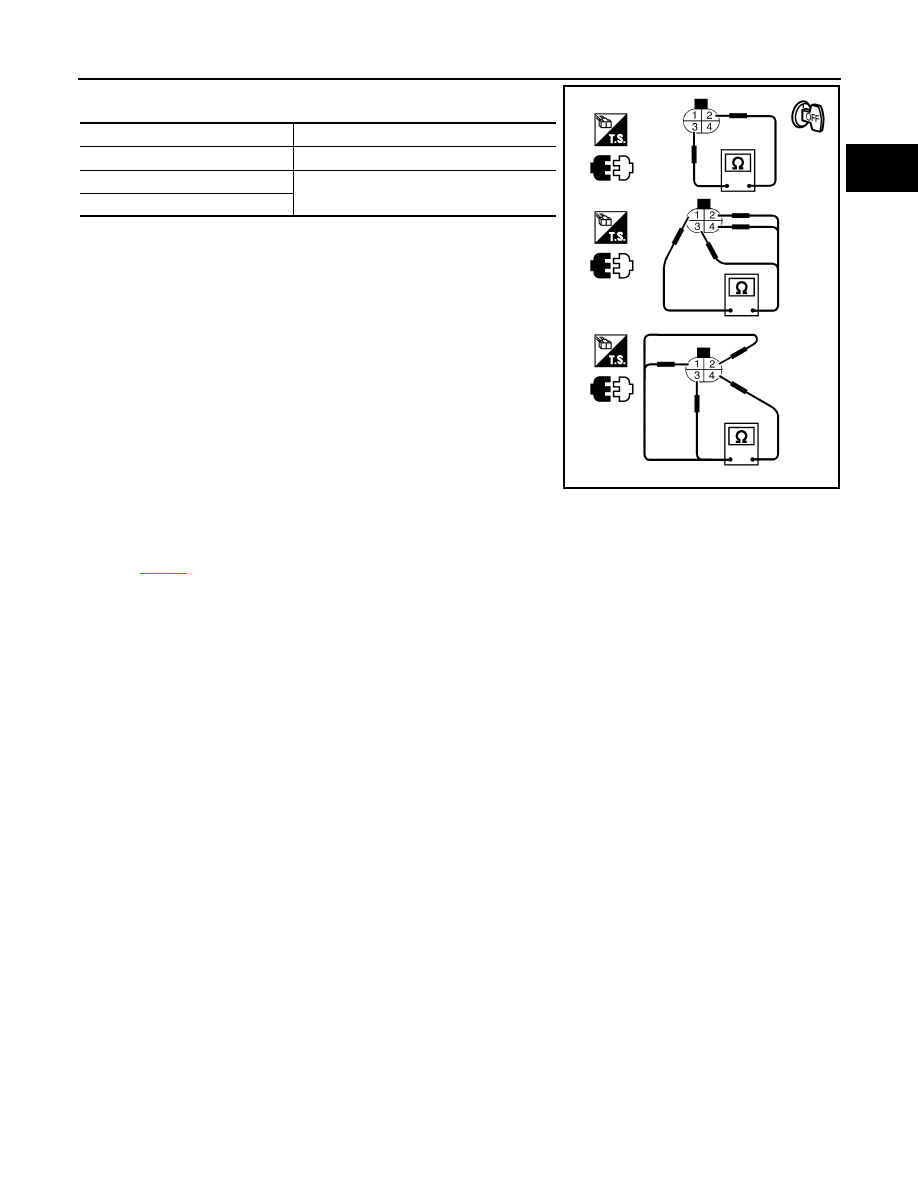
Check resistance between HO2S2 terminals as follows.
2.
If NG, replace heated oxygen sensor 2.
CAUTION:
• Discard any heated oxygen sensor which has been dropped
from a height of more than 0.5 m (19.7 in) onto a hard surface
such as a concrete floor; use a new one.
• Before installing new oxygen sensor, clean exhaust system
threads using Oxygen Sensor Thread Cleaner tool J-43897-18
or J-43897-12 and approved anti-seize lubricant.
Removal and Installation
INFOID:0000000001325980
HEATED OXYGEN SENSOR 2
Terminal No.
Resistance
2 and 3
3.4 - 4.4
Ω
[at 25
°
C (77
°
F)]
1 and 2, 3, 4
∞
Ω
(Continuity should not exist)
4 and 1, 2, 3
PBIB3344E
EC-168
< SERVICE INFORMATION >
[VQ35DE]
DTC P0075, P0081 IVT CONTROL SOLENOID VALVE
DTC P0075, P0081 IVT CONTROL SOLENOID VALVE
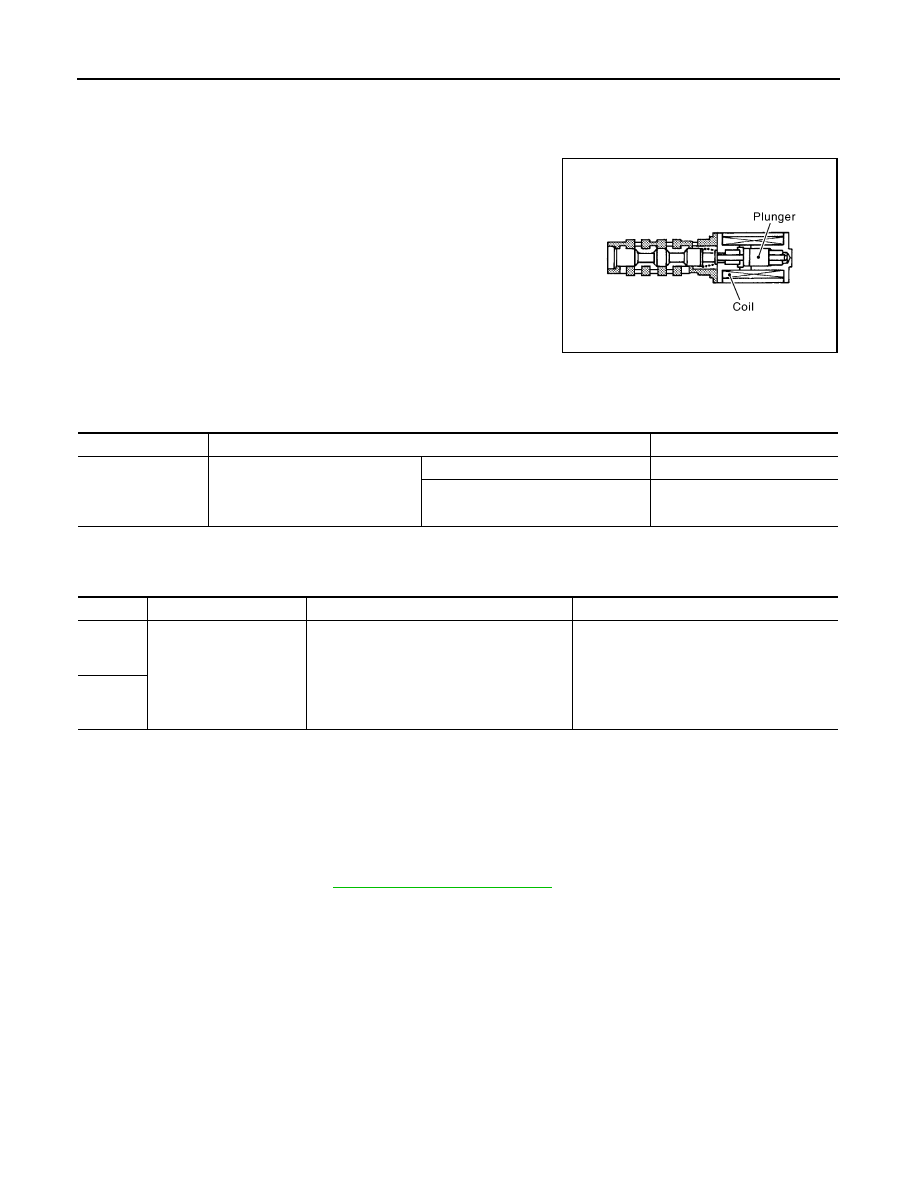
Component Description
INFOID:0000000001325981
Intake valve timing control solenoid valve is activated by ON/OFF
pulse duty (ratio) signals from the ECM.
The intake valve timing control solenoid valve changes the oil
amount and direction of flow through intake valve timing control unit
or stops oil flow.
The longer pulse width advances valve angle.
The shorter pulse width retards valve angle.
When ON and OFF pulse widths become equal, the solenoid valve
stops oil pressure flow to fix the intake valve angle at the control
position.
CONSULT-III Reference Value in Data Monitor Mode
INFOID:0000000001325982
Specification data are reference values.
On Board Diagnosis Logic
INFOID:0000000001325983
DTC Confirmation Procedure
INFOID:0000000001325984
NOTE:
If DTC Confirmation Procedure has been previously conducted, always turn ignition switch OFF and
wait at least 10 seconds before conducting the next test.
1.
Start engine and let it idle for 5 seconds.
2.
Check 1st trip DTC.
3.
If 1st trip DTC is detected, go to
PBIB1842E
MONITOR ITEM
CONDITION
SPECIFICATION
INT/V SOL(B1)
INT/V SOL(B2)
• Engine: After warming up
• Selector lever: P or N
• Air conditioner switch: OFF
• No load
Idle
0% - 2%
When revving engine up to 2,000 rpm
quickly
Approx. 0% - 50%
DTC No.
Trouble diagnosis name
DTC detecting condition
Possible cause
P0075
0075
(Bank 1)
Intake valve timing control
solenoid valve circuit
An improper voltage is sent to the ECM
through intake valve timing control solenoid
valve.
• Harness or connectors
(Intake valve timing control solenoid valve
circuit is open or shorted.)
• Intake valve timing control solenoid valve
P0081
0081
(Bank 2)
Нет комментариевНе стесняйтесь поделиться с нами вашим ценным мнением.
Текст