Infiniti FX35 / FX45. Manual — part 352
DTC P0075, P0081 IVT CONTROL SOLENOID VALVE
EC-169
< SERVICE INFORMATION >
[VQ35DE]
C
D
E
F
G
H
I
J
K
L
M
A
EC
N
P
O
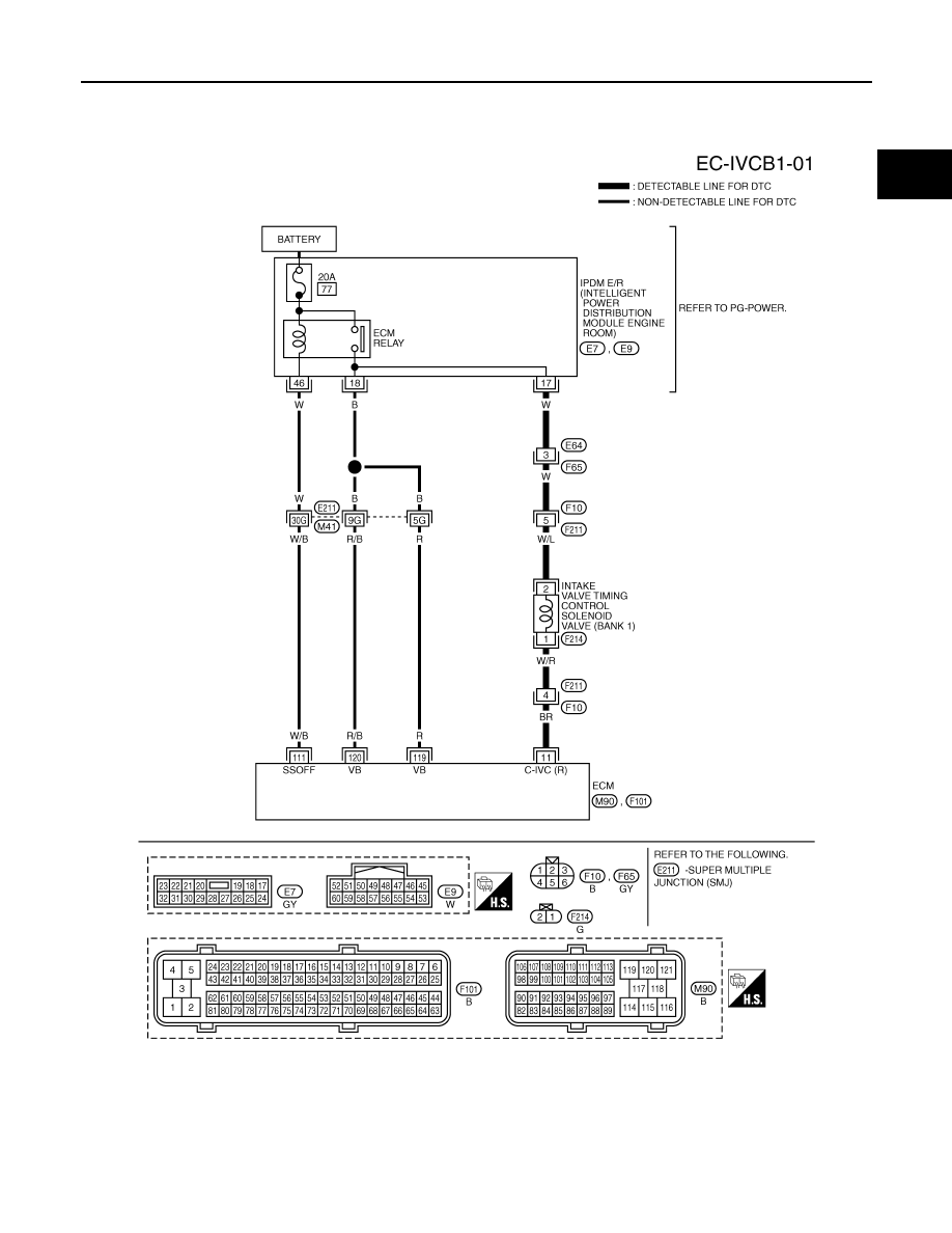
Wiring Diagram
INFOID:0000000001325985
BANK 1
Specification data are reference values and are measured between each terminal and ground.
Pulse signal is measured by CONSULT-III.
CAUTION:
TBWM1394E
EC-170
< SERVICE INFORMATION >
[VQ35DE]
DTC P0075, P0081 IVT CONTROL SOLENOID VALVE
Do not use ECM ground terminals when measuring input/output voltage. Doing so may result in dam-
age to the ECM's transistor. Use a ground other than ECM terminals, such as the ground.
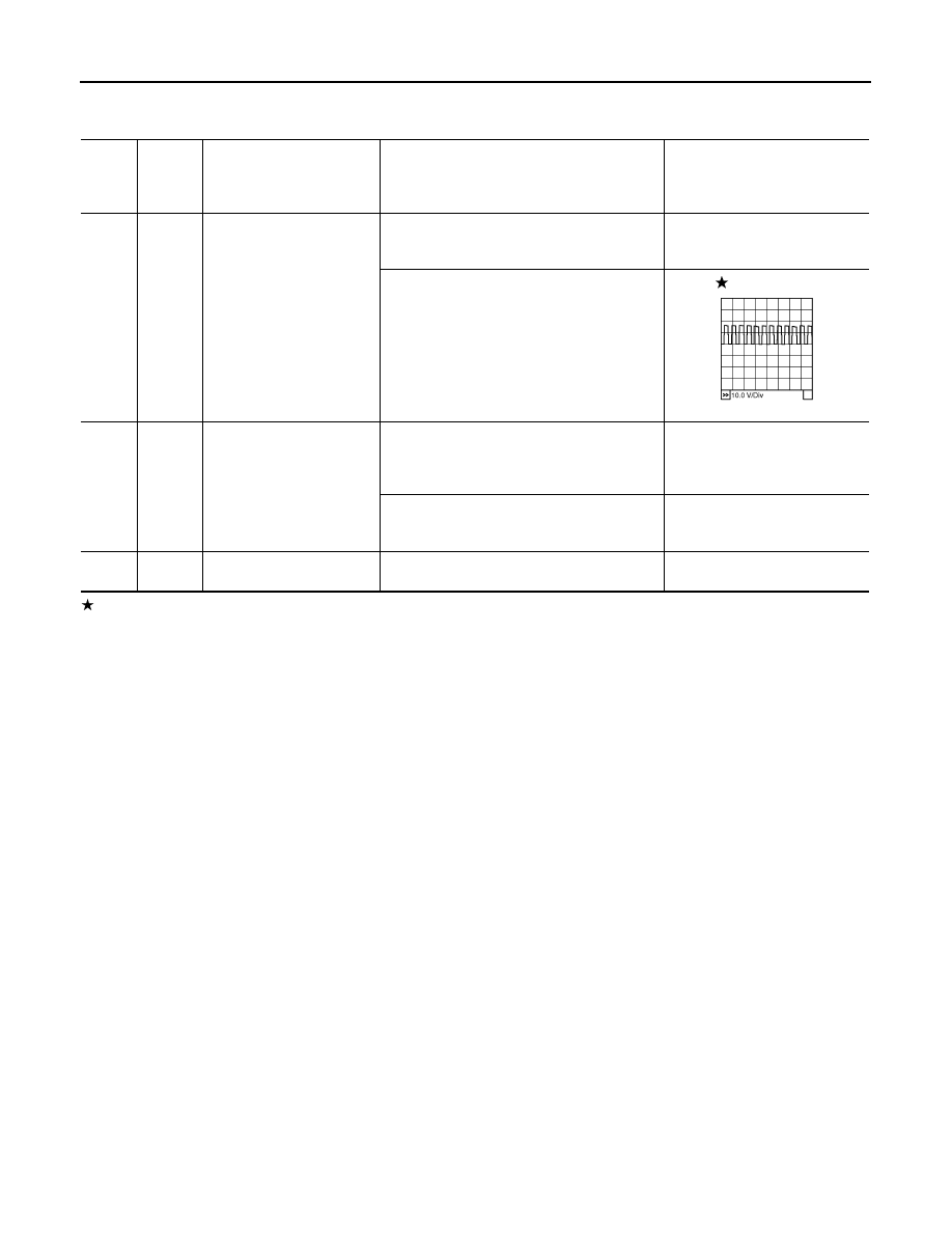
: Average voltage for pulse signal (Actual pulse signal can be confirmed by oscilloscope.)
TER-
MI-
NAL
NO.
WIRE
COLOR
ITEM
CONDITION
DATA (DC Voltage)
11
BR
Intake valve timing control
solenoid valve (bank 1)
[Engine is running]
• Warm-up condition
• Idle speed
BATTERY VOLTAGE
(11 - 14V)
[Engine is running]
• Warm-up condition
• When revving engine up to 2,500 rpm quickly
7 - 12V
111
W/B
ECM relay
(Self shut-off)
[Engine is running]
[Ignition switch: OFF]
• For a few seconds after turning ignition
switch OFF
0 - 1.5V
[Ignition switch: OFF]
• More than a few seconds after turning igni-
tion switch OFF
BATTERY VOLTAGE
(11 - 14V)
119
120
R
R/B
Power supply for ECM
[Ignition switch: ON]
BATTERY VOLTAGE
(11 - 14V)
PBIB1790E
DTC P0075, P0081 IVT CONTROL SOLENOID VALVE
EC-171
< SERVICE INFORMATION >
[VQ35DE]
C
D
E
F
G
H
I
J
K
L
M
A
EC
N
P
O
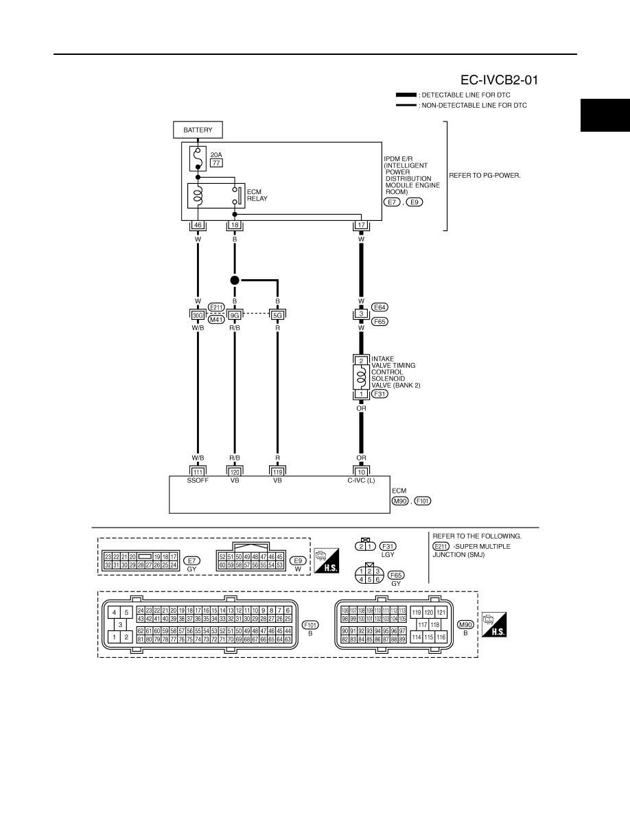
BANK 2
Specification data are reference values and are measured between each terminal and ground.
Pulse signal is measured by CONSULT-III.
CAUTION:
Do not use ECM ground terminals when measuring input/output voltage. Doing so may result in dam-
age to the ECM's transistor. Use a ground other than ECM terminals, such as the ground.
TBWM1395E
EC-172
< SERVICE INFORMATION >
[VQ35DE]
DTC P0075, P0081 IVT CONTROL SOLENOID VALVE
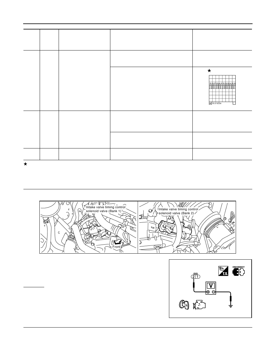
: Average voltage for pulse signal (Actual pulse signal can be confirmed by oscilloscope.)
Diagnosis Procedure
INFOID:0000000001325986
1.
CHECK INTAKE VALVE TIMING CONTROL SOLENOID VALVE POWER SUPPLY CIRCUIT
1.
Turn ignition switch OFF.
2.
Disconnect intake valve timing control solenoid valve harness connector.
3.
Turn ignition switch ON.
4.
Check voltage between intake valve timing control solenoid
valve terminal 2 and ground with CONSULT-III or tester.
OK or NG
OK
>> GO TO 3.
NG
>> GO TO 2.
2.
DETECT MALFUNCTIONING PART
Check the following.
• Harness connectors E64, F65
• Harness connectors F10, F211 (bank 1)
TER-
MI-
NAL
NO.
WIRE
COLOR
ITEM
CONDITION
DATA (DC Voltage)
10
OR
Intake valve timing control
solenoid valve (bank 2)
[Engine is running]
• Warm-up condition
• Idle speed
BATTERY VOLTAGE
(11 - 14V)
[Engine is running]
• Warm-up condition
• When revving engine up to 2,500 rpm quickly
7 - 12V
111
W/B
ECM relay
(Self shut-off)
[Engine is running]
[Ignition switch: OFF]
• For a few seconds after turning ignition
switch OFF
0 - 1.5V
[Ignition switch: OFF]
• More than a few seconds after turning igni-
tion switch OFF
BATTERY VOLTAGE
(11 - 14V)
119
120
R
R/B
Power supply for ECM
[Ignition switch: ON]
BATTERY VOLTAGE
(11 - 14V)
PBIB1790E
Voltage: Battery voltage
PBIB1562E
PBIB0192E
Нет комментариевНе стесняйтесь поделиться с нами вашим ценным мнением.
Текст