Infiniti FX35 / FX45. Manual — part 366
DTC P0131, P0151 A/F SENSOR 1
EC-225
< SERVICE INFORMATION >
[VQ35DE]
C
D
E
F
G
H
I
J
K
L
M
A
EC
N
P
O
: Average voltage for pulse signal (Actual pulse signal can be confirmed by oscilloscope.)
Diagnosis Procedure
INFOID:0000000001326058
1.
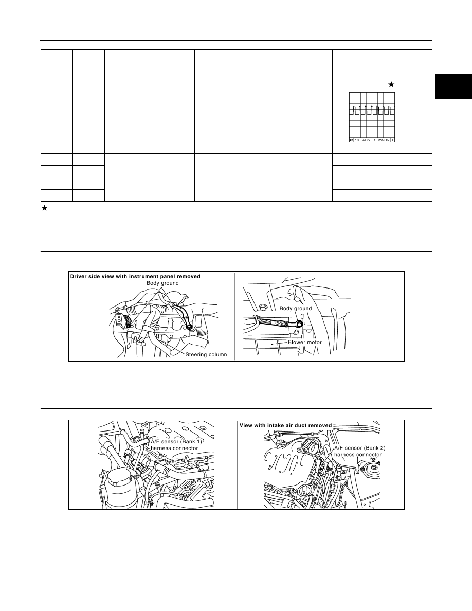
CHECK GROUND CONNECTIONS
1.
Turn ignition switch OFF.
2.
Loosen and retighten ground screw on the body. Refer to
OK or NG
OK
>> GO TO 2.
NG
>> Repair or replace ground connections.
2.
CHECK AIR FUEL RATIO (A/F) SENSOR 1 POWER SUPPLY CIRCUIT
1.
Disconnect air fuel ratio (A/F) sensor 1 harness connector.
2.
Turn ignition switch ON.
TERMI-
NAL
NO.
WIRE
COLOR
ITEM
CONDITION
DATA (DC Voltage)
24
L
A/F sensor 1 heater
(bank 2)
[Engine is running]
• Warm-up condition
• Idle speed
Approximately 5V
57
G
A/F sensor 1 (bank 2)
[Engine is running]
• Warm-up condition
• Idle speed
Approximately 2.6V
58
Y
Approximately 2.3V
76
P
Approximately 3.1V
77
BR
Approximately 2.3V
PBIB1584E
PBIB2625E
PBIB2190E
EC-226
< SERVICE INFORMATION >
[VQ35DE]
DTC P0131, P0151 A/F SENSOR 1
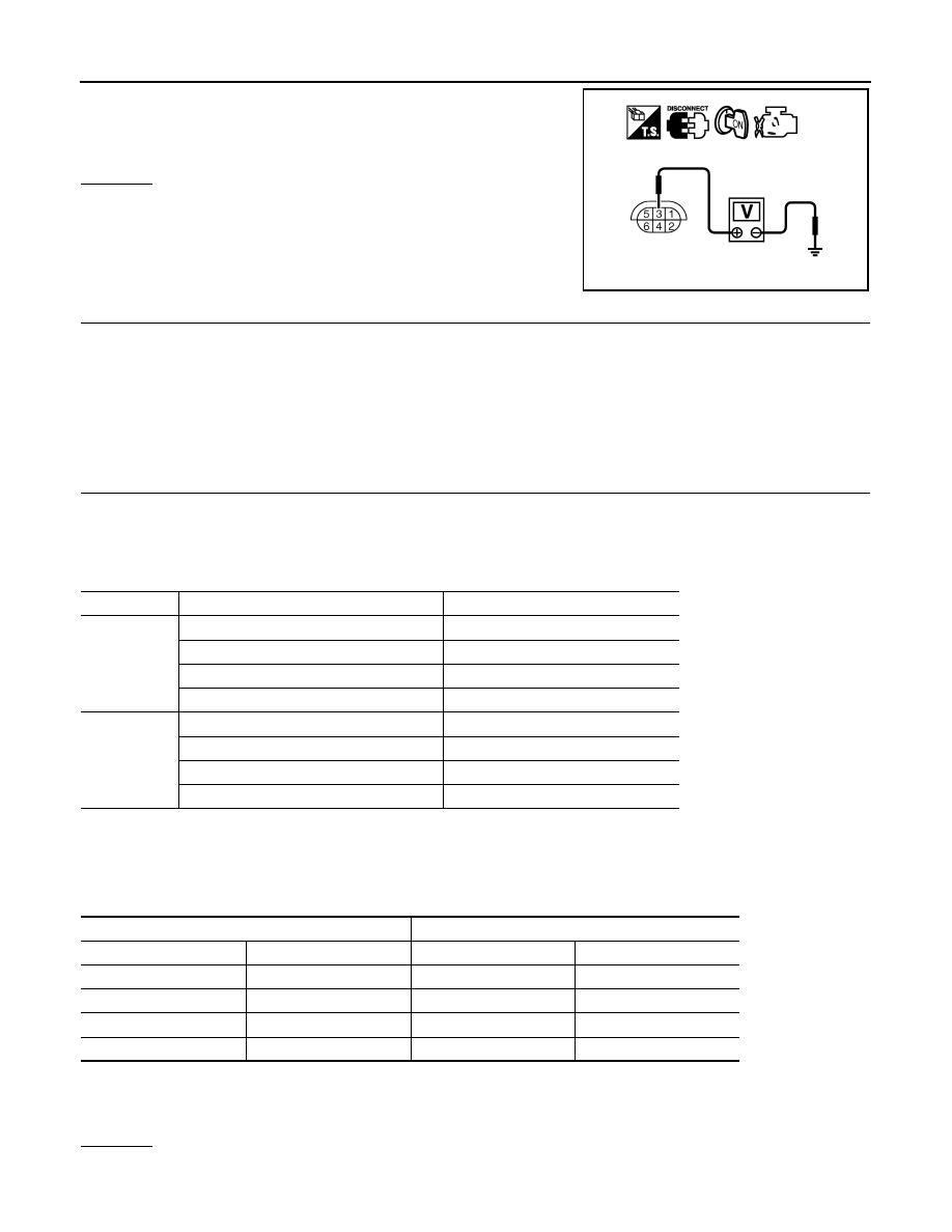
3.
Check voltage between air fuel ratio (A/F) sensor 1 terminal 3
and ground with CONSULT-III or tester.
OK or NG
OK
>> GO TO 4.
NG
>> GO TO 3.
3.
DETECT MALFUNCTIONING PART
Check the following.
• Harness connectors E64, F65
• IPDM E/R harness connector E7
• 10A fuse
• Harness for open or short between air fuel ratio (A/F) sensor 1 and fuse
>> Repair or replace harness or connectors.
4.
CHECK AIR FUEL RATIO (A/F) SENSOR 1 INPUT SIGNAL CIRCUIT
1.
Turn ignition switch OFF.
2.
Disconnect ECM harness connector.
3.
Check harness continuity between the following terminals.
Refer to Wiring Diagram.
4.
Check harness continuity between the following terminals and ground.
Refer to Wiring Diagram.
5.
Also check harness for short to ground and short to power.
OK or NG
OK
>> GO TO 5.
Voltage: Battery voltage
PBIB1683E
A/F sensor 1 terminal
ECM terminal
Bank1
1
16
2
75
5
35
6
56
Bank 2
1
76
2
77
5
57
6
58
Continuity should exist.
Bank 1
Bank 2
A/F sensor 1 terminal
ECM terminal
A/F sensor 1 terminal
ECM terminal
1
16
1
76
2
75
2
77
5
35
5
57
6
56
6
58
Continuity should not exist.

DTC P0131, P0151 A/F SENSOR 1
EC-227
< SERVICE INFORMATION >
[VQ35DE]
C
D
E
F
G
H
I
J
K
L
M
A
EC
N
P
O
NG
>> Repair open circuit or short to ground or short to power in harness or connectors.
5.
CHECK INTERMITTENT INCIDENT
Perform
OK or NG
OK
>> GO TO 6.
NG
>> Repair or replace.
6.
REPLACE AIR FUEL RATIO (A/F) SENSOR 1
Replace malfunctioning air fuel ratio (A/F) sensor 1.
CAUTION:
• Discard any air fuel ratio (A/F) sensor which has been dropped from a height of more than 0.5 m
(19.7 in) onto a hard surface such as a concrete floor; use a new one.
• Before installing new air fuel ratio (A/F) sensor, clean exhaust system threads using Heated Oxygen
Sensor Thread Cleaner tool J-43897-18 or J-43897-12 and approved anti-seize lubricant.
>> INSPECTION END
Removal and Installation
INFOID:0000000001326059
AIR FUEL RATIO (A/F) SENSOR 1
EC-228
< SERVICE INFORMATION >
[VQ35DE]
DTC P0132, P0152 A/F SENSOR 1
DTC P0132, P0152 A/F SENSOR 1
Component Description
INFOID:0000000001326060
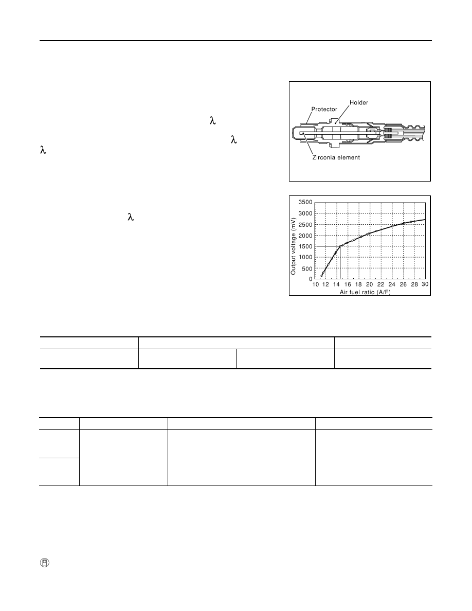
The air fuel ratio (A/F) sensor is a planar dual-cell limit current sen-
sor. The sensor element of the air fuel ratio (A/F) sensor is the com-
bination of a Nernst concentration cell (sensor cell) with an oxygen-
pump cell, which transports ions. It has a heater in the element.
The sensor is capable of precise measurement = 1, but also in the
lean and rich range. Together with its control electronics, the sensor
outputs a clear, continuous signal throughout a wide range (0.7 <
< air).
The exhaust gas components diffuse through the diffusion gap at the
electrode of the oxygen pump and Nernst concentration cell, where
they are brought to thermodynamic balance.
An electronic circuit controls the pump current through the oxygen-
pump cell so that the composition of the exhaust gas in the diffusion
gap remains constant at = 1. Therefore, the air fuel ratio (A/F) sen-
sor is able to indicate air/fuel ratio by this pumping of current. In
addition, a heater is integrated in the sensor to ensure the required
operating temperature of 700 - 800
°
C (1,292 - 1,472
°
F).
CONSULT-III Reference Value in Data Monitor Mode
INFOID:0000000001326061
Specification data are reference values.
On Board Diagnosis Logic
INFOID:0000000001326062
To judge the malfunction, the diagnosis checks that the A/F signal computed by ECM from the air fuel ratio (A/
F) sensor 1 signal is not inordinately high.
DTC Confirmation Procedure
INFOID:0000000001326063
NOTE:
If DTC Confirmation Procedure has been previously conducted, always turn ignition switch OFF and wait at
least 10 seconds before conducting the next test.
TESTING CONDITION:
Before performing the following procedure, confirm that battery voltage is more than 11V at idle.
WITH CONSULT-III
1.
Start engine and warm it up to normal operating temperature.
2.
Select “A/F SEN1 (B1)” or “A/F SEN1 (B2)” in “DATA MONITOR” mode with CONSULT-III.
SEF579Z
SEF580Z
MONITOR ITEM
CONDITION
SPECIFICATION
A/F SEN1 (B1)
A/F SEN1 (B2)
• Engine: After warming up
Maintaining engine speed at
2,000 rpm
Fluctuates around 1.5V
DTC No.
Trouble diagnosis name
DTC detecting condition
Possible Cause
P0132
0132
(Bank 1)
Air fuel ratio (A/F) sensor 1
circuit high voltage
The A/F signal computed by ECM from the air fuel
ratio (A/F) sensor 1 signal is constantly approx.
5V.
• Harness or connectors
[Air fuel ratio (A/F) sensor 1 circuit is
open or shorted.]
• Air fuel ratio (A/F) sensor 1
P0152
0152
(Bank 2)
Нет комментариевНе стесняйтесь поделиться с нами вашим ценным мнением.
Текст