Infiniti FX35 / FX45. Manual — part 365

DTC P0131, P0151 A/F SENSOR 1
EC-221
< SERVICE INFORMATION >
[VQ35DE]
C
D
E
F
G
H
I
J
K
L
M
A
EC
N
P
O
3.
Check “A/F SEN1 (B1)” or “A/F SEN1 (B2)” indication.
If the indication is constantly approx. 0V, go to
If the indication is not constantly approx. 0V, go to next step.
4.
Turn ignition switch OFF, wait at least 10 seconds and then restart engine.
5.
Drive and accelerate vehicle to more than 40 km/h (25 MPH) within 20 seconds after restarting engine.
6.
Maintain the following conditions for about 20 consecutive seconds.
NOTE:
• Keep the accelerator pedal as steady as possible during the cruising.
• If this procedure is not completed within 1 minute after restarting engine at step 4, return to step
4.
7.
Check 1st trip DTC.
8.
If 1st trip DTC is displayed, go to
WITH GST
Follow the procedure “WITH CONSULT-III” above.
ENG SPEED
1,000 - 3,200 rpm
VHCL SPEED SE
More than 40 km/h (25 MPH)
B/FUEL SCHDL
1.5 - 9.0 msec
Gear position
Suitable position
EC-222
< SERVICE INFORMATION >
[VQ35DE]
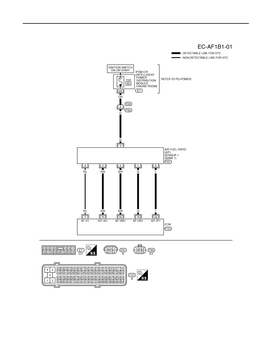
DTC P0131, P0151 A/F SENSOR 1
Wiring Diagram
INFOID:0000000001326057
BANK 1
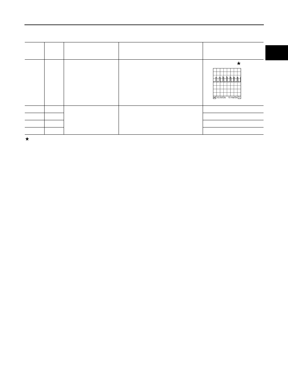
Specification data are reference values and are measured between each terminal and ground.
Pulse signal is measured by CONSULT-III.
CAUTION:
TBWM1598E
DTC P0131, P0151 A/F SENSOR 1
EC-223
< SERVICE INFORMATION >
[VQ35DE]
C
D
E
F
G
H
I
J
K
L
M
A
EC
N
P
O
Do not use ECM ground terminals when measuring input/output voltage. Doing so may result in dam-
age to the ECM's transistor. Use a ground other than ECM terminals, such as the ground.
: Average voltage for pulse signal (Actual pulse signal can be confirmed by oscilloscope.)
TERMI-
NAL
NO.
WIRE
COLOR
ITEM
CONDITION
DATA (DC Voltage)
2
R/L
A/F sensor 1 heater
(bank 1)
[Engine is running]
• Warm-up condition
• Idle speed
Approximately 5V
16
G
A/F sensor 1 (bank 1)
[Engine is running]
• Warm-up condition
• Idle speed
Approximately 3.1V
35
B/R
Approximately 2.6V
56
L
Approximately 2.3V
75
R/B
Approximately 2.3V
PBIB1584E
EC-224
< SERVICE INFORMATION >
[VQ35DE]
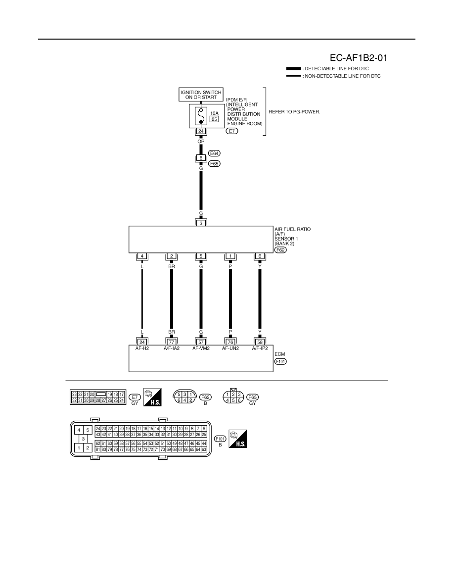
DTC P0131, P0151 A/F SENSOR 1
BANK 2
Specification data are reference values and are measured between each terminal and ground.
Pulse signal is measured by CONSULT-III.
CAUTION:
Do not use ECM ground terminals when measuring input/output voltage. Doing so may result in dam-
age to the ECM's transistor. Use a ground other than ECM terminals, such as the ground.
TBWM1599E
Нет комментариевНе стесняйтесь поделиться с нами вашим ценным мнением.
Текст