Infiniti FX35 / FX45. Manual — part 306
CLOCK
DI-99
< SERVICE INFORMATION >
C
D
E
F
G
H
I
J
L
M
A
B
DI
N
O
P
2.
Remove A/T console finisher. Refer to
IP-11, "Removal and Installation"
3.
Remove instrument clock finisher. Refer to
IP-11, "Removal and Installation"
.
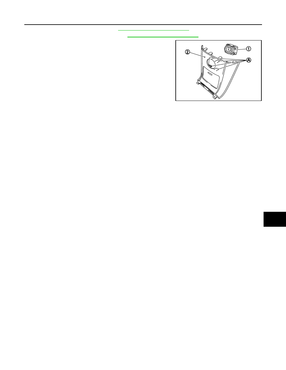
4.
Remove tabs (A), and remove clock (1) from instrument clock
finisher (2).
INSTALLATION
Installation is the reverse order of removal.
SKIB8488E
DI-100
< SERVICE INFORMATION >
REAR VIEW MONITOR
REAR VIEW MONITOR
System Description
INFOID:0000000001328529
• The rear view monitor is equipped to check the rearward of the vehicle with display when A/T selector lever
is in reverse position.
• The lines of vehicle sides and the distance from the rear end of the vehicle are provided on display as a
guide. It allows the driver to know the distance between the vehicle and a rearward object, and the width of
the vehicle much easier.
POWER SUPPLY AND GROUND
Power is supplied at all time
• through 10A fuse [No. 19, located in fuse block (J/B)]
• to rear view camera control unit terminal 1.
When ignition switch is in ACC or ON position, power is supplied
• through 10A fuse [No. 6, located in fuse block (J/B)]
• to rear view camera control unit terminal 2.
When ignition switch is in ON or START position, power is supplied
• through 10A fuse (No. 83, located in IPDM E/R)
• to back-up lamp relay terminals 1 and 3.
Ground is supplied
• to rear view camera control unit terminal 3
• through grounds M35, M45 and M85.
AV COMMUNICATION LINE
Rear view camera control unit is connected to the following units with AV communication line. Each unit trans-
mits/receives data with AV communication line.
• NAVI control unit
• Display
• Display control unit
• A/C and AV switch
REAR VIEW CAMERA OPERATION
When A/T selector lever is reverse position, power is supplied
• through back-up lamp relay terminal 2
• to TCM terminal 7.
Then back-up lamp relay is energized,
• from back-up lamp relay terminal 5
• to rear view camera control unit terminal 4.
Then, rear view camera control unit is sent camera ON signal
• through rear view camera control unit terminal 8
• to rear view camera terminal 1.
An image taken by rear view camera is sent
• through rear view camera terminals 3 and 4
• to rear view camera control unit terminals 10 and 9.
Then an image is sent
• through rear view camera control unit terminals 12 and 14
• to the display terminals 15 and 16.
An image of rear view will be projected on the display.
Side Distance Guideline
When A/T selector lever is in reverse position, rear view camera control unit is sent rear view camera guideline
image
• through rear view camera control unit terminals 12 and 14
• to the display terminals 15 and 16.
Rear view camera guideline will be projected on the display.
Display shows image from rear view camera image and rear view camera guideline.
REAR VIEW MONITOR
DI-101
< SERVICE INFORMATION >
C
D
E
F
G
H
I
J
L
M
A
B
DI
N
O
P
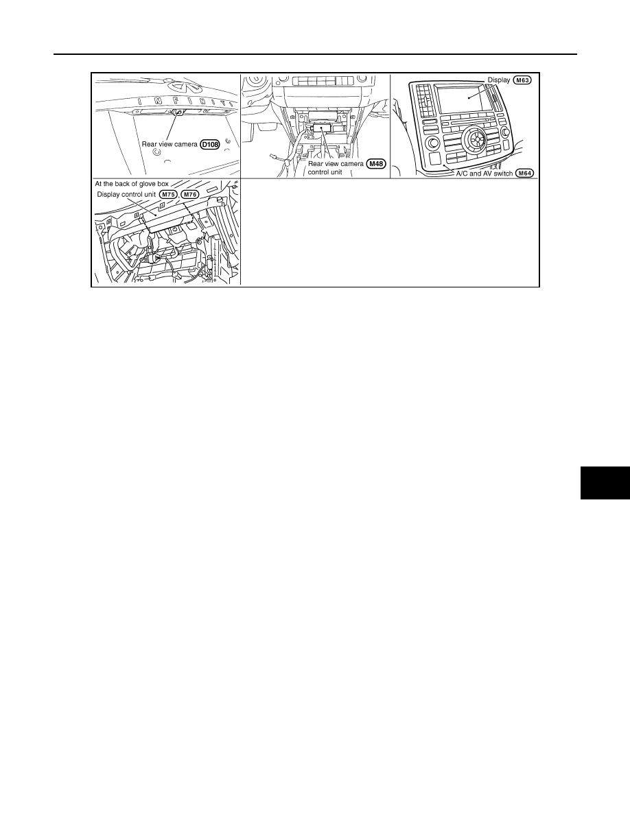
Component Parts and Harness Connector Location
INFOID:0000000001328530
SKIB8489E
DI-102
< SERVICE INFORMATION >
REAR VIEW MONITOR
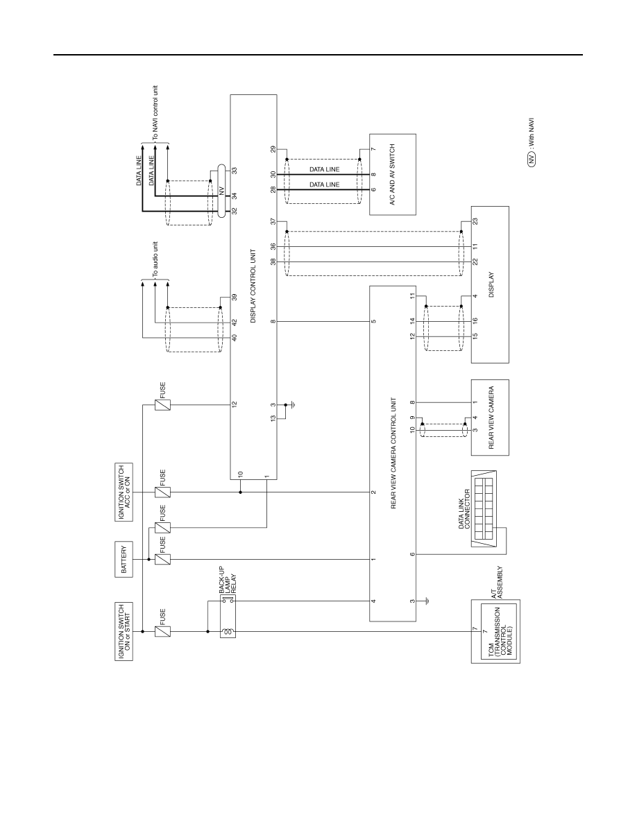
Schematic
INFOID:0000000001328531
TKWM4361E
Нет комментариевНе стесняйтесь поделиться с нами вашим ценным мнением.
Текст