Infiniti FX35 / FX45. Manual — part 326
ON BOARD DIAGNOSTIC (OBD) SYSTEM
EC-65
< SERVICE INFORMATION >
[VQ35DE]
C
D
E
F
G
H
I
J
K
L
M
A
EC
N
P
O
• Sea level
• Flat road
• Ambient air temperature: 20 - 30
°
C (68 - 86
°
F)
• Diagnosis is performed as quickly as possible under normal conditions.
Under different conditions [For example: ambient air temperature other than 20 - 30
°
C (68 - 86
°
F)], diagno-
sis may also be performed.
Pattern 1:
• The engine is started at the engine coolant temperature of
−
10 to 35
°
C (14 to 95
°
F)
(where the voltage between the ECM terminal 73 and ground is 3.0 - 4.3V).
• The engine must be operated at idle speed until the engine coolant temperature is greater than 70
°
C
(158
°
F) (where the voltage between the ECM terminal 73 and ground is lower than 1.4V).
• The engine is started at the fuel tank temperature of warmer than 0
°
C (32
°
F) (where the voltage
between the ECM terminal 107 and ground is less than 4.1V).
Pattern 2:
• When steady-state driving is performed again even after it is interrupted, each diagnosis can be conducted.
In this case, the time required for diagnosis may be extended.
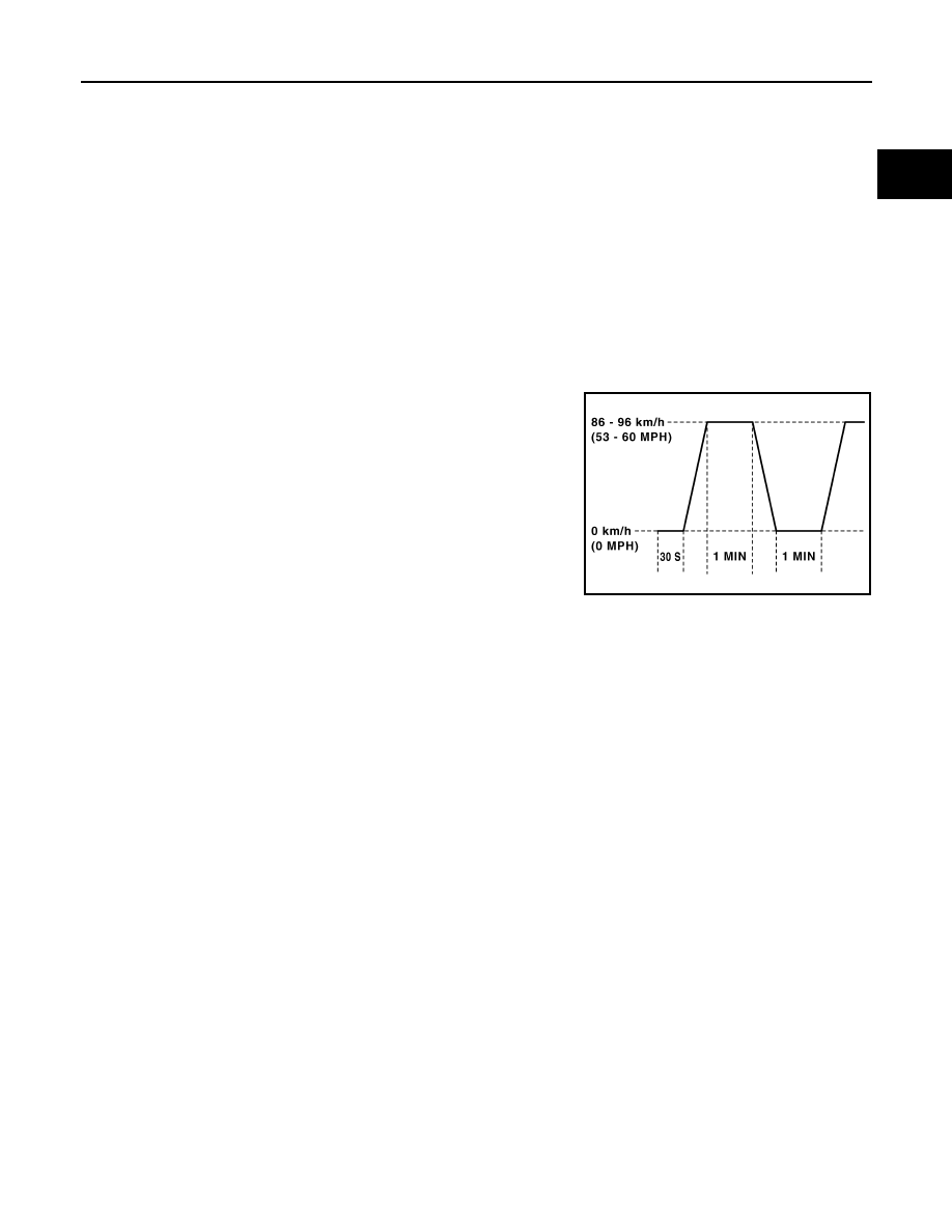
Pattern 3:
• Operate vehicle following the driving pattern shown in the figure.
• replace the accelerator pedal during decelerating vehicle speed
from 90km/h(56MPH) to 0km/h(0MPH).
Pattern 4:
• The accelerator pedal must be held very steady during steady-
state driving.
• If the accelerator pedal is moved, the test must be conducted all
over again.
*1: Depress the accelerator pedal until vehicle speed is 90 km/h (56
MPH), then release the accelerator pedal and keep it released for
more than 10 seconds. Depress the accelerator pedal until vehicle
speed is 90 km/h (56 MPH) again.
*2: Checking the vehicle speed with GST is advised.
Suggested Transmission Gear Position
Set the selector lever in the D position.
TEST VALUE AND TEST LIMIT
The following is the information specified in Service $06 of SAE J1979.
The test value is a parameter used to determine whether a system/circuit diagnostic test is OK or NG while
being monitored by the ECM during self-diagnosis. The test limit is a reference value which is specified as the
maximum or minimum value and is compared with the test value being monitored.
These data (test value and test limit) are specified by On Board Monitor ID(OBDMID), Test ID (TID), Unit and
Scaling ID and can be displayed on the GST screen.
The items of the test value and test limit will be displayed with GST screen which items are provided by the
ECM. (eg., if the bank 2 is not applied on this vehicle, only the items of the bank 1 is displayed)
PBIB2244E

EC-66
< SERVICE INFORMATION >
[VQ35DE]
ON BOARD DIAGNOSTIC (OBD) SYSTEM
Item
OBD-
MID
Self-diagnostic test item
DTC
Test value and Test
limit
(GST display)
Description
TID
Unit and
Scaling
ID
HO2S
01H
Air fuel ratio (A/F) sensor 1
(Bank 1)
P0131
83H
0BH
Minimum sensor output voltage
for test cycle
P0131
84H
0BH
Maximum sensor output voltage
for test cycle
P0130
85H
0BH
Minimum sensor output voltage
for test cycle
P0130
86H
0BH
Maximum sensor output voltage
for test cycle
P0133
87H
04H
Response rate: Response ratio
(Lean to Rich)
P0133
88H
04H
Response rate: Response ratio
(Rich to Lean)
P2A00
89H
84H
The amount of shift in air fuel ratio
P2A00
8AH
84H
The amount of shift in air fuel ratio
P0130
8BH
0BH
Difference in sensor output volt-
age
P0133
8CH
83H
Response gain at the limited fre-
quency
02H
Heated oxygen sensor 2
(Bank 1)
P0138
07H
0CH
Minimum sensor output voltage
for test cycle
P0137
08H
0CH
Maximum sensor output voltage
for test cycle
P0138
80H
0CH
Sensor output voltage
P0139
81H
0CH
Difference in sensor output volt-
age
03H
Heated oxygen sensor 3
(Bank 1)
P0143
07H
0CH
Minimum sensor output voltage
for test cycle
P0144
08H
0CH
Maximum sensor output voltage
for test cycle
P0146
80H
0CH
Sensor output voltage
P0145
81H
0CH
Difference in sensor output volt-
age

ON BOARD DIAGNOSTIC (OBD) SYSTEM
EC-67
< SERVICE INFORMATION >
[VQ35DE]
C
D
E
F
G
H
I
J
K
L
M
A
EC
N
P
O
HO2S
05H
Air fuel ratio (A/F) sensor 1
(Bank 2)
P0151
83H
0BH
Minimum sensor output voltage
for test cycle
P0151
84H
0BH
Maximum sensor output voltage
for test cycle
P0150
85H
0BH
Minimum sensor output voltage
for test cycle
P0150
86H
0BH
Maximum sensor output voltage
for test cycle
P0153
87H
04H
Response rate: Response ratio
(Lean to Rich)
P0153
88H
04H
Response rate: Response ratio
(Rich to Lean)
P2A03
89H
84H
The amount of shift in air fuel ratio
P2A03
8AH
84H
The amount of shift in air fuel ratio
P0150
8BH
0BH
Difference in sensor output volt-
age
P0153
8CH
83H
Response gain at the limited fre-
quency
06H
Heated oxygen sensor 2
(Bank 2)
P0158
07H
0CH
Minimum sensor output voltage
for test cycle
P0157
08H
0CH
Maximum sensor output voltage
for test cycle
P0158
80H
0CH
Sensor output voltage
P0159
81H
0CH
Difference in sensor output volt-
age
07H
Heated oxygen sensor 3
(Bank2)
P0163
07H
0CH
Minimum sensor output voltage
for test cycle
P0164
08H
0CH
Maximum sensor output voltage
for test cycle
P0166
80H
0CH
Sensor output voltage
P0165
81H
0CH
Difference in sensor output volt-
age
CATA-
LYST
21H
Three way catalyst function
(Bank1)
P0420
80H
01H
O2 storage index
P0420
82H
01H
Switching time lag engine exhaust
index value
P2423
83H
0CH
Difference in 3rd O2 sensor out-
put voltage
P2423
84H
84H
O2 storage index in HC trap cata-
lyst
22H
Three way catalyst function
(Bank2)
P0430
80H
01H
O2 storage index
P0430
82H
01H
Switching time lag engine exhaust
index value
P2424
83H
0CH
Difference in 3rd O2 sensor out-
put voltage
P2424
84H
84H
O2 storage index in HC trap cata-
lyst
Item
OBD-
MID
Self-diagnostic test item
DTC
Test value and Test
limit
(GST display)
Description
TID
Unit and
Scaling
ID

EC-68
< SERVICE INFORMATION >
[VQ35DE]
ON BOARD DIAGNOSTIC (OBD) SYSTEM
EGR
SYSTEM
31H
EGR function
P0400
80H
96H
Low Flow Faults: EGR temp
change rate (short term)
P0400
81H
96H
Low Flow Faults: EGR temp
change rate (long term)
P0400
82H
96H
Low Flow Faults: Difference be-
tween max EGR temp and EGR
temp under idling condition
P0400
83H
96H
Low Flow Faults: Max EGR temp
P1402
84H
96H
High Flow Faults: EGR temp in-
crease rate
EVAP
SYSTEM
39H
EVAP control system leak
(Cap Off)
P0455
80H
0CH
Difference in pressure sensor out-
put voltage before and after pull
down
3BH
EVAP control system leak
(Small leak)
P0442
80H
05H
Leak area index (for more than
0.04inch)
3CH
EVAP control system
(Very small leak)
P0456
80H
05H
Leak area index (for more than
0.02inch)
P0456
81H
FDH
Maximum internal pressure of
EVAP system during monitoring
3DH
Purge flow system
P0441
83H
0CH
Difference in pressure sensor out-
put voltage before and after vent
control value close
O2 SEN-
SOR
HEATER
41H
A/F sensor 1 heater
(Bank 1)
Low Input:P0031
High Input:P0032
81H
0BH
Converted value of Heater electric
current to voltage
42H
Heated oxygen sensor 2
(Bank 1)
Low Input:P0037
High Input:P0038
80H
0CH
Converted value of Heater electric
current to voltage
43H
Heated oxygen sensor 3
(Bank 1)
P0043
80H
0CH
Converted value of Heater electric
current to voltage
45H
A/F sensor 1 heater
(Bank 2)
Low Input:P0051
High Input:P0052
81H
0BH
Converted value of Heater electric
current to voltage
46H
Heated oxygen sensor 2
(Bank 2)
Low Input:P0057
High Input:P0058
80H
0CH
Converted value of Heater electric
current to voltage
47H
Heated oxygen sensor 3
(Bank 2)
P0063
80H
0CH
Converted value of Heater electric
current to voltage
SEC-
OND-
ARY AIR
71H
Secondary Air system
P0411
80H
01H
Secondary Air Injection System
Incorrect Flow Detected
Bank1: P0491
Bank2: P0492
81H
01H
Secondary Air Injection System
Insufficient Flow
P2445
82H
01H
Secondary Air Injection System
Pump Stuck Off
P2448
83H
01H
Secondary Air Injection System
High Airflow
Bank1: P2440
Bank2: P2442
84H
01H
Secondary Air Injection System
Switching Valve Stuck Open
P2440
85H
01H
Secondary Air Injection System
Switching Valve Stuck Open
P2444
86H
01H
Secondary Air Injection System
Pump Stuck On
Item
OBD-
MID
Self-diagnostic test item
DTC
Test value and Test
limit
(GST display)
Description
TID
Unit and
Scaling
ID
Нет комментариевНе стесняйтесь поделиться с нами вашим ценным мнением.
Текст