Infiniti FX35 / FX45. Manual — part 683
CYLINDER BLOCK
EM-249
< SERVICE INFORMATION >
[VK45DE]
C
D
E
F
G
H
I
J
K
L
M
A
EM
N
P
O
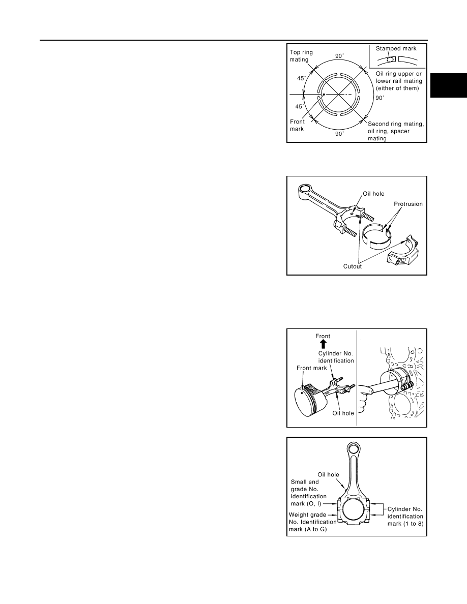
• Position each ring with the gap as shown in the figure, refer-
ring to the piston front mark.
• Install top ring and second ring with the stamped surface fac-
ing upward.
12. Install connecting rod bearings to connecting rod and connecting rod bearing cap.
• Before installing connecting rod bearings, apply engine oil to the bearing surface (inside). Do not apply
engine oil to the back surface, but thoroughly clean it.
• When installing, align the connecting rod bearing stopper pro-
trusion with the cutout of connecting rod and connecting rod
bearing cap to install.
• Ensure the oil holes on connecting rod and that on the corre-
sponding bearing are aligned.
13. Install piston and connecting rod assembly to crankshaft.
• Position the crankshaft pin corresponding to connecting rod to be installed onto the bottom dead center.
• Apply engine oil sufficiently to the cylinder bore, piston and crankshaft pin journal.
• Match the cylinder position with the cylinder No. on connecting rod to install.
• Be sure that front mark on piston head is facing front of engine.
• Using piston ring compressor [SST: EM03470000 (J8037)],
install piston with the front mark on the piston head facing the
front of engine.
CAUTION:
Be careful not to damage cylinder wall and crankshaft pin,
resulting from an interference of the connecting rod big
end.
14. Install connecting rod bearing cap.
• Match the stamped cylinder number marks on connecting rod
with those on cap to install.
15. Tighten connecting rod nuts as follows:
a.
Apply new engine oil to the threads and seats of connecting rod bolts and nuts.
b.
Tighten connecting rod nuts.
Stamped mark
Top ring
: R
Second ring
: 2R
PBIC0100E
PBIC2370E
PBIC0102E
PBIC2164E
EM-250
< SERVICE INFORMATION >
[VK45DE]
CYLINDER BLOCK
c.
Then tighten all connecting rod nuts 60 degrees clockwise.
(Angle tightening)
CAUTION:
Use angle wrench (SST) to check tightening angle. Do not
make judgment by visual inspection.
• After tightening connecting rod nuts, make sure that crank-
shaft rotates smoothly.
• Check the connecting rod side clearance. Refer to
"Inspection After Disassembly"
.
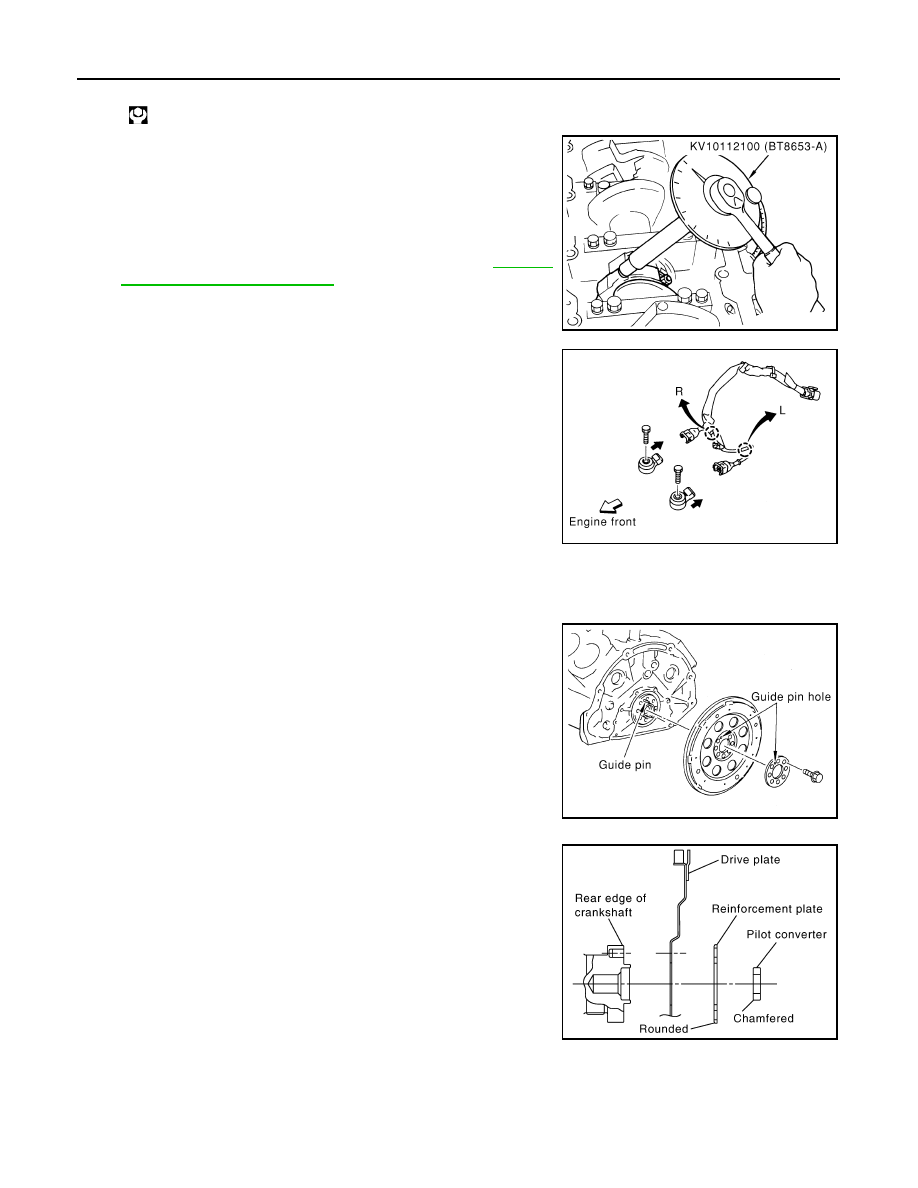
16. Install knock sensor.
• Install it with its connector facing the rear of engine.
• Install the sub-harness with its shorter branch line to the right
bank.
CAUTION:
• Do not tighten mounting bolts while holding connector.
• If any impact by dropping is applied to knock sensor,
replace it with new one.
NOTE:
• Make sure that there is no foreign material on the cylinder
block mating surface and the back surface of knock sensor.
• Make sure that knock sensor does not interfere with other
parts.
17. Note the following, and assemble in the reverse order of disassembly after this step.
Drive plate
• When installing drive plate to crankshaft, be sure to correctly
align crankshaft side guide pin and drive plate side guide pin
hole.
- If these are not aligned correctly, engine runs roughly and
“MIL” turns on.
• Install drive plate, reinforcement plate and pilot converter (if
not installed in step 4) as shown in the figure.
• Face chamfered or rounded edge side to crankshaft.
• Holding ring gear with ring gear stopper [SST: J-45476].
• Tighten mounting bolts crosswise over several times.
• When install pilot converter, using drift [outer diameter: approx.
35 mm (1.38 in)]. Press-fit as far as it will go.
CAUTION:
Make sure that guide pin is installed at the rear end of
crankshaft.
How to Select Piston and Bearing
INFOID:0000000001325805
DESCRIPTION
: 14.7 N·m (1.5 kg-m, 11 ft-lb)
PBIC0104E
PBIC0105E
PBIC0106E
PBIC1965E
CYLINDER BLOCK
EM-251
< SERVICE INFORMATION >
[VK45DE]
C
D
E
F
G
H
I
J
K
L
M
A
EM
N
P
O
*: For the service parts, the grade for fitting cannot be selected between piston pin and connecting rod. (Only “0” grade is available.) The
information at the shipment from the plant is described as a reference.
• The identification grade stamped on each part is the grade for the dimension measured in new condition.
This grade cannot apply to reused parts.
• For reused or repaired parts, measure the dimension accurately. Determine the grade by comparing the
measurement with the values of each selection table.
• For details of the measurement method of each part, the reuse standards, and the selection method of the
selective fitting parts, refer to the text.
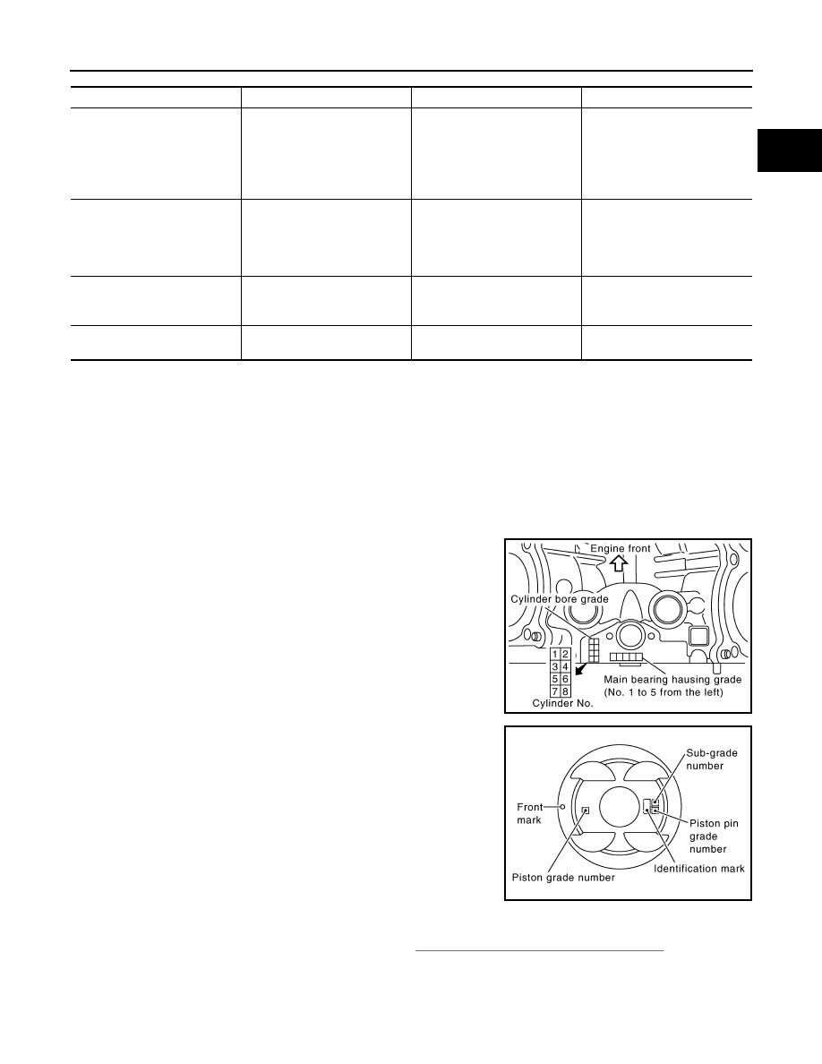
HOW TO SELECT PISTON
When New Cylinder Block is Used:
Check the cylinder bore grade (“1”, “2” or “3”) on the rear upper side
between cylinder block banks, and select piston of the same grade.
NOTE:
Piston is available with piston pin as a set for the service part. (Only
“0” grade piston pin is available.)
When Cylinder Block is Reused:
1.
Measure the cylinder bore inner diameter. Refer to
EM-256, "Inspection After Disassembly"
.
2.
Determine the bore grade by comparing the measurement with the values the “Cylinder bore inner diame-
ter” of the “Piston Selection Table”. Select piston of the same grade.
Piston Selection Table
Selection points
Selection parts
Selection items
Selection methods
Between cylinder block and
crankshaft
Main bearing
Main bearing grade
(bearing thickness)
Determined by match of cylin-
der block bearing housing
grade (inner diameter of hous-
ing) and crankshaft journal
grade (outer diameter of jour-
nal)
Between crankshaft and con-
necting rod
Connecting rod bearing
Connecting rod bearing grade
(bearing thickness)
Combining service grades for
connecting rod big end diame-
ter and crankshaft pin outer di-
ameter determine connecting
rod bearing selection.
Between cylinder block and pis-
ton
Piston and piston pin assembly
(Piston is available together
with piston pin as assembly.)
Piston grade
(piston skirt diameter)
Piston grade = cylinder bore
grade (inner diameter of bore)
Between piston and connecting
rod*
—
—
—
PBIC2371E
PBIC2372E
EM-252
< SERVICE INFORMATION >
[VK45DE]
CYLINDER BLOCK
Unit: mm (in)
NOTE:
• Piston is available together with piston pin as assembly.
• Piston pin (piston pin hole) grade is provided only for the parts installed at the plant. For service parts, no pis-
ton pin grades can be selected. (Only “0” grade is available.)
• No second grade mark is available on piston.
HOW TO SELECT CONNECTING ROD BEARING
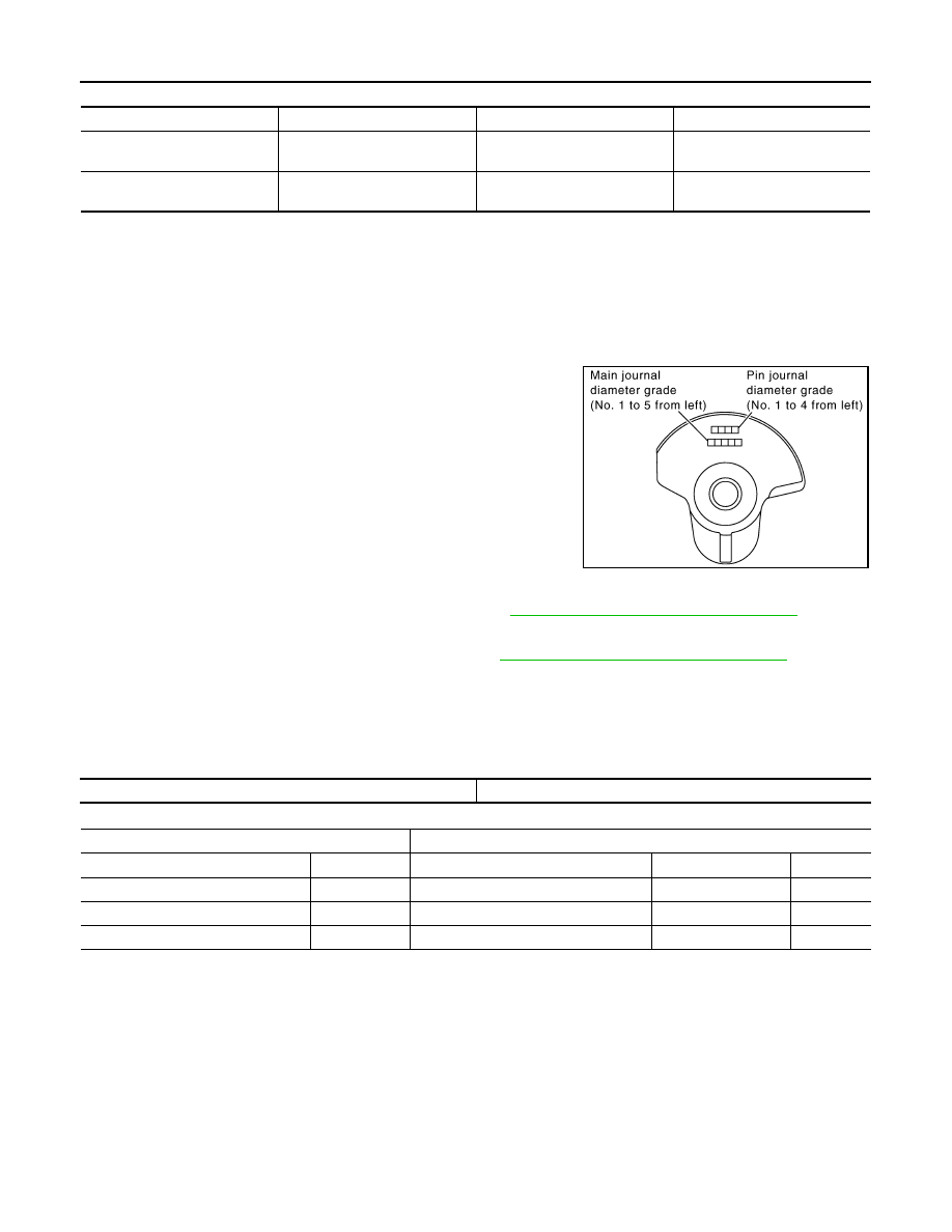
When New Connecting Rod and Crankshaft are Used:
Check pin diameter grade (“0”, “1” or “2”) on front of crankshaft, and
select connecting rod bearing of the same grade.
NOTE:
There is no grading for connecting rod big end diameter.
When Crankshaft and Connecting Rod are Reused:
1.
Measure the connecting rod big end diameter. Refer to
EM-256, "Inspection After Disassembly"
.
2.
Make sure that the connecting rod big end diameter is within the standard value.
3.
Measure the crankshaft pin journal diameter. Refer to
EM-256, "Inspection After Disassembly"
.
4.
Determine the grade of crankshaft pin diameter grade by corresponding to the measured dimension in
“Crankshaft pin journal diameter” column of “Connecting Rod Bearing Selection Table”.
5.
Select connecting rod bearing of the same grade.
Connecting Rod Bearing Selection Table
Unit: mm (in)
Unit: mm (in)
Under Size Bearings Usage Guide
• When the specified connecting rod bearing oil clearance is not obtained with standard size connecting rod
bearings, use undersize (US) bearings.
• When using undersize (US) bearing, measure the connecting rod bearing inner diameter with bearing
installed, and grind crankshaft pin so that the connecting rod bearing oil clearance satisfies the standard.
CAUTION:
Grade
1
2 (or no mark)
3
Cylinder bore inner diameter
93.000 - 93.010
(3.6614 - 3.6618)
93.010 - 93.020
(3.6618 - 3.6622)
93.020 - 93.030
(3.6622 - 3.6626)
Piston skirt diameter
92.980 - 92.990
(3.6606 - 3.6610)
92.990 - 93.000
(3.6610 - 3.6614)
93.000 - 93.010
(3.6614 - 3.6618)
PBIC2374E
Connecting rod big end diameter
55.000 - 55.013 (2.1654 - 2.1659)
Crankshaft
Connecting rod bearing
Crankshaft pin journal diameter
Grade (Mark)
Dimension (Bearing thickness range)
Bearing grade No.
Color
51.968 - 51.974 (2.0460 - 2.0462)
0
1.500 - 1.503 (0.0591 - 0.0592)
STD 0
No color
51.962 - 51.968 (2.0457 - 2.0460)
1
1.503 - 1.506 (0.0592 - 0.0593)
STD 1
Brown
51.956 - 51.962 (2.0455 - 2.0457)
2
1.506 - 1.509 (0.0593 - 0.0594)
STD 2
Green
Нет комментариевНе стесняйтесь поделиться с нами вашим ценным мнением.
Текст