Infiniti FX35 / FX45. Manual — part 681
CYLINDER BLOCK
EM-241
< SERVICE INFORMATION >
[VK45DE]
C
D
E
F
G
H
I
J
K
L
M
A
EM
N
P
O
CYLINDER BLOCK
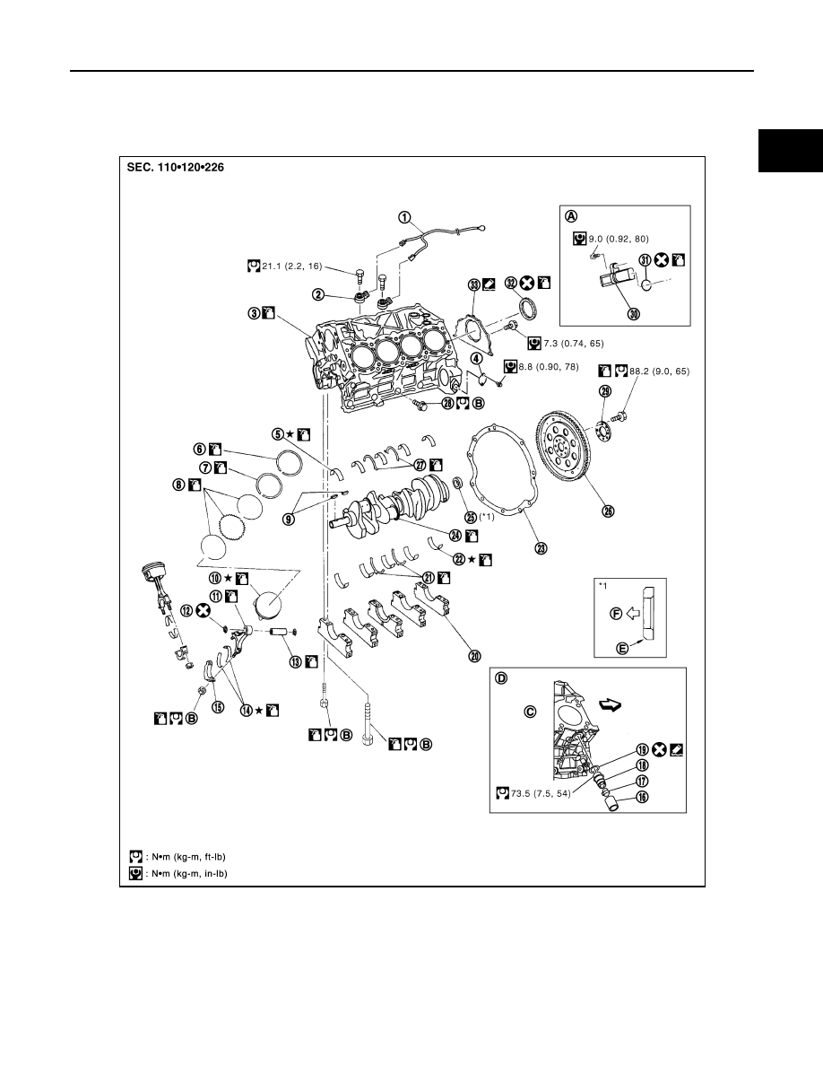
Component
INFOID:0000000001325803
1.
Knock sensor sub harness
2.
Knock sensor
3.
Cylinder block
4.
Cover
5.
Main bearing
6.
Top ring
7.
Second ring
8.
Oil ring
9.
Crankshaft key
10.
Piston
11.
Connecting rod
12.
Snap ring
13.
Piston pin
14.
Connecting rod bearing
15.
Connecting rod bearing cap
16.
Block heater protector
17.
Connector cap
18.
Cylinder block heater
19.
Gasket
20.
Main bearing cap
21.
Thrust bearing
PBIC4691E
EM-242
< SERVICE INFORMATION >
[VK45DE]
CYLINDER BLOCK
• Refer to
for symbols in the figure.
Disassembly and Assembly
INFOID:0000000001325804
DISASSEMBLY
NOTE:
Explained here is how to disassemble with engine stand supporting transmission surface. When using differ-
ent type of engine stand, note with difference in steps and etc.
1.
Remove engine assembly from vehicle, and separate front suspension member, transmission and front
final drive from engine. Refer to
.
2.
Remove the parts that may restrict installation of engine to widely use engine stand.
NOTE:
The procedure is described assuming that you use widely use engine holding the surface, to which trans-
mission is installed.
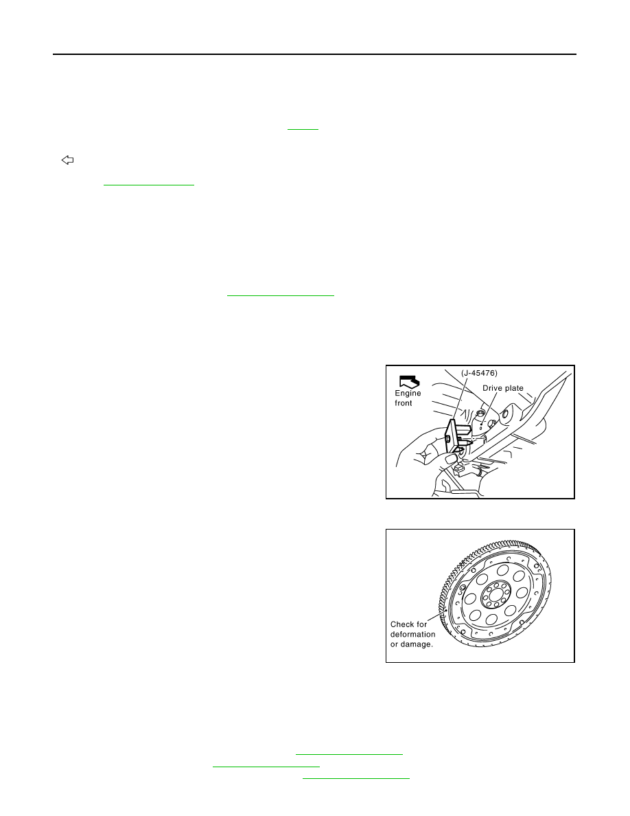
a.
Remove drive plate.
• Holding ring gear with ring gear stopper (SST).
• Loosen mounting bolts diagonally order.
CAUTION:
• Do not disassemble drive plate.
• Do not place drive plate with signal plate facing down.
• When handling signal plate, take care not to damage or
scratch it.
• Handle signal plate in a manner that prevents it from
becoming magnetized.
b.
Remove engine rear plate.
3.
Lift engine with hoist to install it onto widely use engine stand.
CAUTION:
Use engine stand that has a load capacity [approximately 240 kg (529 lb) or more] large enough for
supporting the engine weight.
• If the load capacity of stand is not adequate, remove the following parts beforehand to reduce the poten-
tial risk of overturning stand.
- Intake manifolds (upper and lower): Refer to
.
- Exhaust manifold: Refer to
.
- Fuel tube and fuel injector assembly: Refer to
.
22.
Main bearing
23.
Rear plate
24.
Crankshaft
25.
Pilot converter
26.
Drive plate
27.
Thrust bearing
28.
Side bolt
29.
Reinforcement plate
30.
Crankshaft position sensor (POS)
31.
O-ring
32.
Rear oil seal
33.
Rear oil seal retainer
A.
Refererence: Installed on transmis-
sion
B.
C.
Right bank
D.
Cylinder block heater (For Canada)
E.
Chamfered
F.
Crankshaft side
: Engine front
PBIC1656E
PBIC2367E

CYLINDER BLOCK
EM-243
< SERVICE INFORMATION >
[VK45DE]
C
D
E
F
G
H
I
J
K
L
M
A
EM
N
P
O
- A/C compressor: Refer to
- Ignition coil: Refer to
.
- Rocker cover: Refer to
.
- Other removable brackets
NOTE:
The figure shows an example of widely use engine stand that
can hold mating surface of transmission with drive plate and rear
plate removed.
CAUTION:
Before removing the hanging chains, make sure the engine
stand is stable and there is no risk of overturning.
4.
Drain engine oil. Refer to
5.
Drain engine coolant from inside engine by removing water
drain plugs “B” as shown in the figure.
6.
Remove the following parts and related parts (The parts listed in step 3 are not included here).
• Oil pan and oil strainer: Refer to
.
• Crankshaft pulley, front cover and timing chain: Refer to
.
• Camshaft: Refer to
.
7.
Remove knock sensor.
CAUTION:
Carefully handle sensor, avoiding shocks.
8.
Remove piston and connecting rod assembly as follows:
• Before removing piston and connecting rod assembly, check the connecting rod side clearance. Refer to
EM-256, "Inspection After Disassembly"
a.
Position crankshaft pin corresponding to connecting rod to be removed onto the bottom dead center.
b.
Remove connecting rod bearing cap.
c.
Using hammer handle or similar tool, push piston and connect-
ing rod assembly out to the cylinder head side.
CAUTION:
Be careful not to damage the cylinder wall and crankshaft
pin, resulting from an interference of the connecting rod big
end.
9.
Remove connecting rod bearings from connecting rod and connecting rod bearing cap.
CAUTION:
Identify installation positions, and store them without mixing them up.
PBIC0085E
PBIC1265E
PBIC0086E
EM-244
< SERVICE INFORMATION >
[VK45DE]
CYLINDER BLOCK
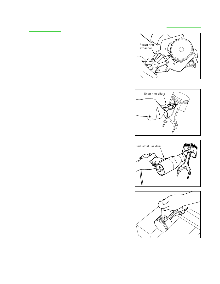
10. Remove piston rings from piston.
• Before removing the piston rings, check the piston ring side clearance. Refer to
• Use piston ring expander (commercial service tool).
CAUTION:
• When removing piston rings, be careful not to damage
piston.
• Be careful not to damage piston rings by expanding them
excessively.
11. Remove piston from connecting rod as follows:
a.
Using snap ring pliers, remove the snap rings.
b.
Heat piston to 60 to 70
°
C (140 to 158
°
F) with industrial use drier
or equivalent.
c.
Push out piston pin with stick of outer diameter approximately 20
mm (0.8 in).
12. Remove rear oil seal retainer from cylinder block.
• Insert screwdriver or similar tool between rear end of crankshaft counter weight and rear oil seal
retainer, and separate liquid gasket to remove.
CAUTION:
Be careful not to damage the mating surfaces.
13. Using screwdriver or similar tool, and lever off rear oil seal from rear oil seal retainer.
14. Remove main bearing cap as follows:
PBIC0087E
PBIC0088E
PBIC0089E
EMM0072D
Нет комментариевНе стесняйтесь поделиться с нами вашим ценным мнением.
Текст