Infiniti FX35 / FX45. Manual — part 664
AIR CLEANER AND AIR DUCT
EM-173
< SERVICE INFORMATION >
[VK45DE]
C
D
E
F
G
H
I
J
K
L
M
A
EM
N
P
O
AIR CLEANER AND AIR DUCT
Component
INFOID:0000000001325771
• Refer to
Removal and Installation
INFOID:0000000001325772
REMOVAL
1.
Remove engine cover with power tool. Refer to
2.
Disconnect harness connector from mass air flow sensor.
3.
Disconnect vacuum hose and PCV hose.
4.
Remove air duct (inlet), power duct, air cleaner case and mass air flow sensor assembly, air duct and res-
onator assembly disconnecting their joints.
• Add marks as necessary for easier installation.
5.
Remove mass air flow sensor from air cleaner case.
CAUTION:
Handle mass air flow sensor with following cares.
• Do not shock it.
• Do not disassemble it.
• Do not touch its sensor.
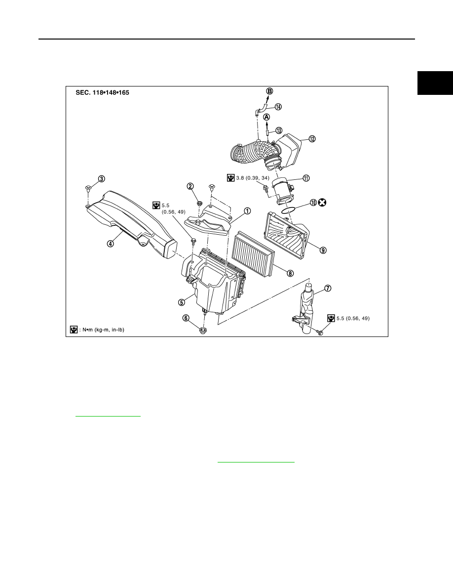
1.
Power duct
2.
Blind plug
3.
Clip
4.
Air duct (inlet)
5.
Air cleaner case
6.
Mounting rubber
7.
Resonator
8.
Air cleaner filter
9.
Air cleaner case
10.
O-ring
11.
Mass air flow sensor
12. Air duct and resonator assembly
13.
Vacuum hose
14.
PCV hose
A.
To VIAS control solenoid valve
B.
To rocker cover (left bank)
PBIC4551E
EM-174
< SERVICE INFORMATION >
[VK45DE]
AIR CLEANER AND AIR DUCT
INSPECTION AFTER REMOVAL
Inspect air duct and resonator assembly for crack or tear.
• If anything found, replace air duct and resonator assembly.
INSTALLATION
Note the following, and install in the reverse order of removal.
• Align marks. Attach each joint. Screw clamps firmly.
Changing Air Cleaner Filter
INFOID:0000000001325773
REMOVAL
1.
Remove air duct (inlet), power duct, air cleaner case and mass air flow sensor assembly.
2.
Remove air cleaner filter from air cleaner case.
INSTALLATION
Install in the reverse order of removal.
INTAKE MANIFOLD
EM-175
< SERVICE INFORMATION >
[VK45DE]
C
D
E
F
G
H
I
J
K
L
M
A
EM
N
P
O
INTAKE MANIFOLD
Component
INFOID:0000000001325774
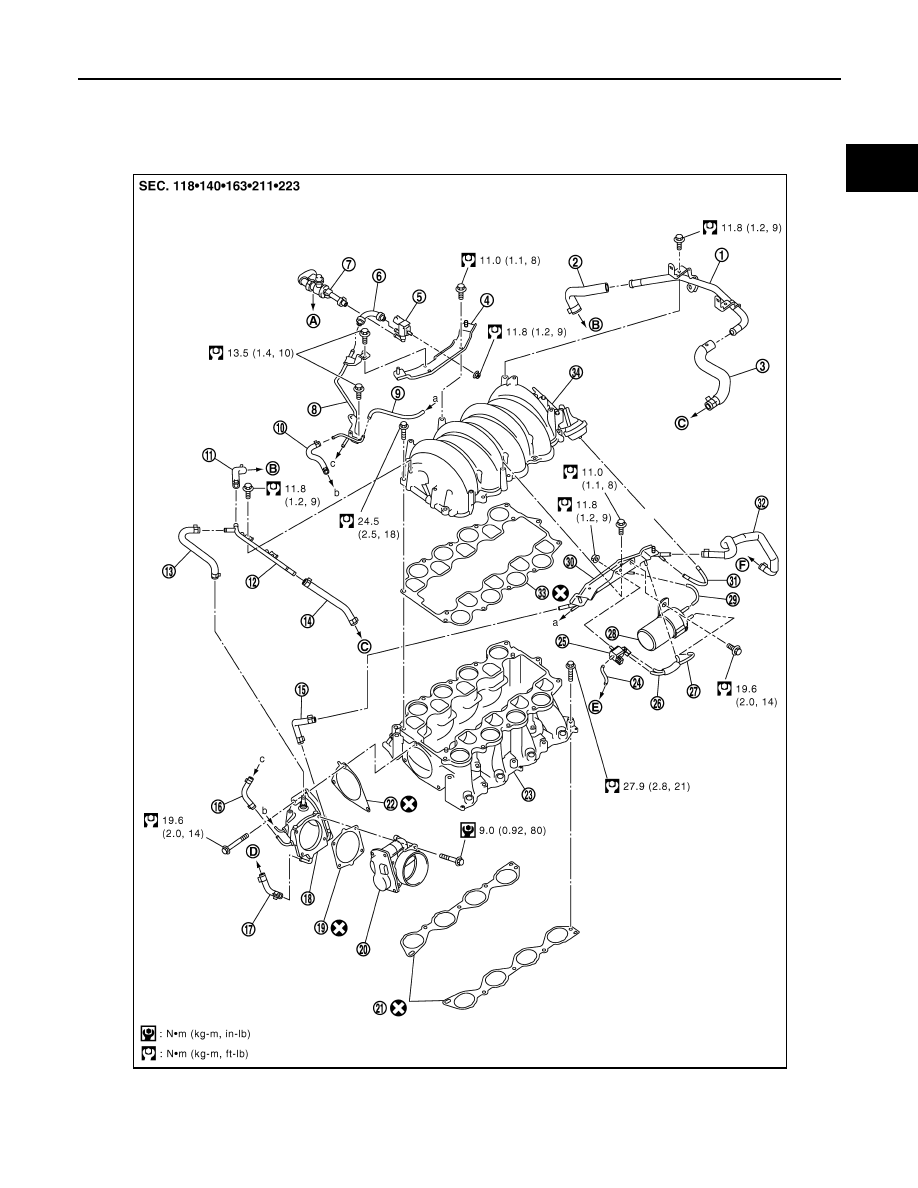
1.
PCV tube
2.
PCV hose
3.
PCV hose
4.
Engine cover bracket (RH)
5.
EVAP canister purge control sole-
noid valve
6.
EVAP hose
PBIC4555E

EM-176
< SERVICE INFORMATION >
[VK45DE]
INTAKE MANIFOLD
• Refer to
for symbols in the figure.
Removal and Installation
INFOID:0000000001325775
REMOVAL
WARNING:
To avoid the danger of being scalded, never drain the engine coolant when the engine is hot.
1.
Remove engine cover with power tool.
2.
Release fuel pressure. Refer to
.
3.
Remove air duct (inlet), power duct, air cleaner case and air duct and resonator assembly. Refer to
.
4.
Drain engine coolant from radiator. Refer to
CO-37, "Changing Engine Coolant"
.
CAUTION:
• Perform this step when the engine is cold.
• Do not spill engine coolant on drive belts.
7.
EVAP service port
8.
EVAP tube
9.
Vacuum hose
10.
Vacuum hose
11.
PCV hose
12.
PCV tube
13.
PCV hose
14.
PCV hose
15.
Water hose
16.
EVAP hose
17.
Water hose
18.
Intake manifold adapter
19.
Gasket
20.
Electric throttle control actuator
21.
Gasket
22.
Gasket
23.
Intake manifold (lower)
24.
Vacuum hose
25.
VIAS control solenoid valve
26.
Vacuum hose
27.
Vacuum hose
28.
Vacuum tank
29.
Vacuum hose
30.
Engine cover bracket (LH)
31.
Vacuum hose
32.
Water hose
33.
Gasket
34.
Intake manifold (upper)
A.
To centralized under-floor piping
B.
To rocker cover (right bank)
C.
To rocker cover (left bank)
D.
To thermostat housing
E.
To air duct and resonator assembly
F.
To heater pipe
PBIC4553E
Нет комментариевНе стесняйтесь поделиться с нами вашим ценным мнением.
Текст