Infiniti FX35 / FX45. Manual — part 663
ENGINE ROOM COVER
EM-169
< SERVICE INFORMATION >
[VK45DE]
C
D
E
F
G
H
I
J
K
L
M
A
EM
N
P
O
ENGINE ROOM COVER
Component
INFOID:0000000001325763
Removal and Installation
INFOID:0000000001325764
REMOVAL
CAUTION:
Do not damage or scratch cover when installing or removing.
• Major parts and inspection points under each cover are as follows: (numbered as in the figure)
INSTALLATION
Install in the reverse order of removal.
1.
Mount nut
2.
Battery cover
3.
Air duct (inlet)
4.
Clip
5.
Engine cover
PBIC4550E
1 : Upper side of engine assembly and power steering reservoir tank
2 : Relay and battery
3 : Engine assembly front side, drive belts and cooling fan
EM-170
< SERVICE INFORMATION >
[VK45DE]
DRIVE BELTS
DRIVE BELTS
Component
INFOID:0000000001325765
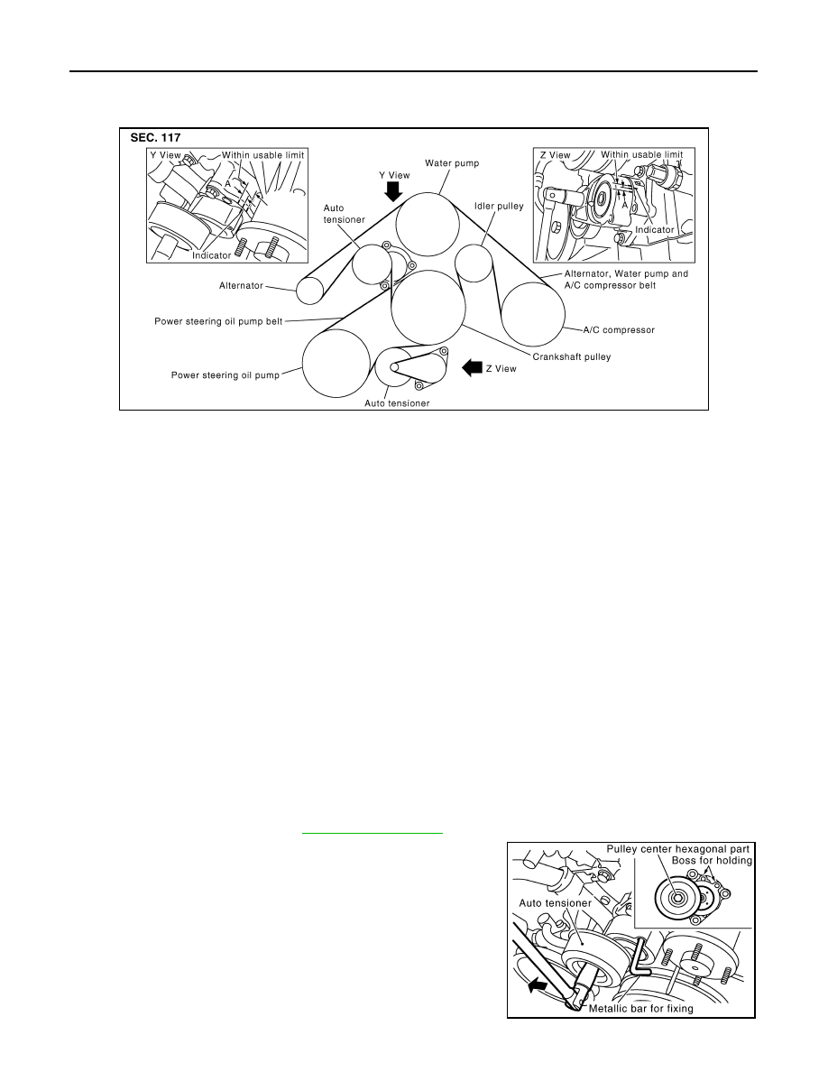
Checking Drive Belts
INFOID:0000000001325766
WARNING:
Be sure to perform when engine is stopped.
• Remove air duct (inlet) when inspecting drive belt for alternator, water pump and A/C compressor.
• Remove front engine undercover with power tool when inspecting power steering oil pump belt.
• Make sure that indicator (single line notch) of each auto tensioner is within the allowable working range
(between three line notches).
NOTE:
• Check auto tensioner indication when engine is cold.
• When new drive belt is installed, the range should be “A”.
• The indicator notch is located on the moving side of auto tensioner for alternator, water pump and A/C
compressor belt, while it is found on the fixed side for power steering oil pump belt.
• Visually check entire belt for wear, damage or cracks.
• If the indicator is out of allowable working range or belt is damaged, replace belt.
Tension Adjustment
INFOID:0000000001325767
Belt tensioning is not necessary, as it is automatically adjusted by auto tensioner.
Removal and Installation
INFOID:0000000001325768
REMOVAL
Alternator, Water Pump and A/C Compressor Belt
1.
Remove air duct (inlet). Refer to
2.
With box wrench, and while securely holding the hexagonal part
in pulley center of auto tensioner, move wrench handle in the
direction of arrow (loosening direction of tensioner).
CAUTION:
• Avoid placing hand in a location where pinching may
occur if the holding tool accidentally comes off.
• Do not loosen the hexagonal part in center of drive belt
auto-tensioner pulley (Do not turn it clockwise). If turned
clockwise, the complete drive belt auto-tensioner must be
replaced as a unit, including the pulley.
PBIC2331E
PBIC2976E
DRIVE BELTS
EM-171
< SERVICE INFORMATION >
[VK45DE]
C
D
E
F
G
H
I
J
K
L
M
A
EM
N
P
O
3.
Under the above condition, insert a metallic bar of approximately 6 mm (0.24 in) in diameter (hexagonal
bar wrench shown as example in the figure) through the holding boss to lock auto tensioner pulley arm.
• Leave auto tensioner pulley arm locked until belt is installed again.
4.
Remove alternator, water pump and A/C compressor belt.
Power Steering Oil Pump Belt
1.
Remove air duct (inlet). Refer to
2.
Remove front engine undercover with power tool.
3.
Remove alternator, water pump and A/C compressor belt. Refer to "Alternator, Water Pump and A/C
Compressor Belt".
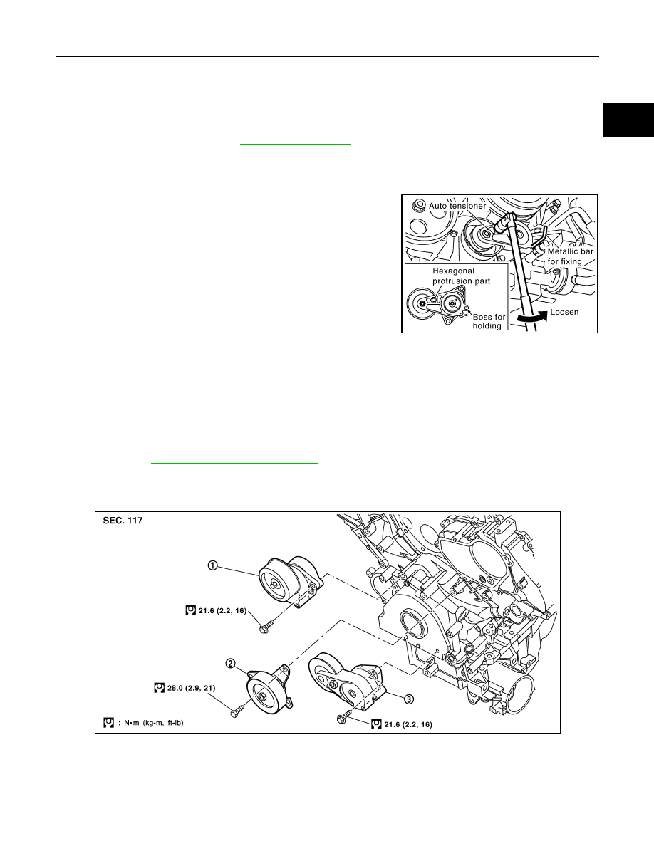
4.
While securely holding the hexagonal protrusion part of auto
tensioner pulley with box wrench, move wrench handle in the
direction of arrow (loosening direction of tensioner).
CAUTION:
Avoid placing hand in a location where pinching may occur
if holding tool accidentally comes off.
5.
Under the above condition, insert a metallic bar of approximately
6 mm (0.24 in) in diameter (hexagonal bar wrench shown as
example in the figure) through the holding boss to lock auto ten-
sioner pulley arm.
• Leave auto tensioner pulley arm locked until belt is installed
again.
6.
Remove power steering oil pump belt.
INSTALLATION
Note the following, and install in the reverse order of removal.
CAUTION:
• Make sure belt is securely installed around all pulleys.
• Make sure belt is correctly engaged with the pulley groove.
• Check for engine oil and engine coolant are not adhered belt and pulley groove.
• Check that belt tension is within the allowable working range, using indicator notch on auto ten-
sioner. Refer to
EM-170, "Checking Drive Belts"
Component
INFOID:0000000001325769
CAUTION:
The complete drive belt auto-tensioner must be replaced as a unit, including the pulley.
PBIC1543E
1.
Auto tensioner ( Used for alternator,
water pump and A/C compressor)
2.
Idler pulley
3.
Auto tensioner (Used for power steer-
ing oil pump belt)
PBIC2788E
EM-172
< SERVICE INFORMATION >
[VK45DE]
DRIVE BELTS
Drive Belt Auto Tensioner and Idler Pulley
INFOID:0000000001325770
REMOVAL
1.
Remove air duct (inlet). Refer to
2.
Remove front engine undercover with power tool.
3.
Remove drive belts. Refer to
EM-170, "Removal and Installation"
• Keep auto tensioner pulley arm locked after belt is removed.
4.
Remove auto tensioner and idler pulley with power tool.
• Keep auto tensioner pulley arm locked to install or remove auto tensioner.
CAUTION:
Do not loosen the hexagonal part in center of drive belt auto-tensioner pulley (Do not turn it clock-
wise). If turned clockwise, the complete drive belt auto-tensioner must be replaced as a unit,
including the pulley.
INSTALLATION
Install in the reverse order of removal.
CAUTION:
Do not swap the pulley between new and old drive belt auto-tensioner.
Нет комментариевНе стесняйтесь поделиться с нами вашим ценным мнением.
Текст