Infiniti FX35 / FX45. Manual — part 200
REMOTE KEYLESS ENTRY SYSTEM
BL-67
< SERVICE INFORMATION >
C
D
E
F
G
H
J
K
L
M
A
B
BL
N
O
P
Without CONSULT-III
Check voltage between BCM connector and ground.
OK or NG
OK
>> Back door switch circuit is OK.
NG
>> GO TO 2.
2.
CHECK HARNESS CONTINUITY
1.
Turn ignition switch OFF.
2.
Disconnect BCM and back door closure motor connector.
3.
Check continuity between BCM connector B14 terminal 58 and
back door closure motor connector D109 terminal 7.
4.
Check continuity between BCM connector B14 terminal 58 and
ground.
OK or NG
OK
>> GO TO 3.
NG
>> Repair or replace harness.
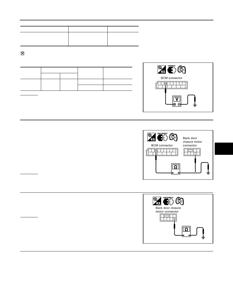
3.
CHECK GROUND CIRCUIT
Check continuity between back door closure motor connector D109
terminal 8 and ground.
OK or NG
OK
>> GO TO 4.
NG
>> Repair or replace harness.
4.
CHECK BACK DOOR SWITCH
Monitor item
Condition
DATA MONITOR
BACK DOOR SW
OPEN
↓
CLOSE
ON
↓
OFF
Connector
Terminals (Wire color)
Condition
Voltage (V)
(Approx.)
(+)
(–)
B14
58 (L)
Ground
OPEN
0
CLOSE
9
PIIA6229E
58 (L) – 7 (L)
: Continuity should exist.
58 (L) – Ground
: Continuity should not exist.
PIIA6226E
8 (B) – Ground
: Continuity should exist.
PIIA6170E
BL-68
< SERVICE INFORMATION >
REMOTE KEYLESS ENTRY SYSTEM
Check continuity between back door closure motor D109 terminals 7
and 8.
OK or NG
OK
>> GO TO 5.
NG
>> Replace back door closure motor.
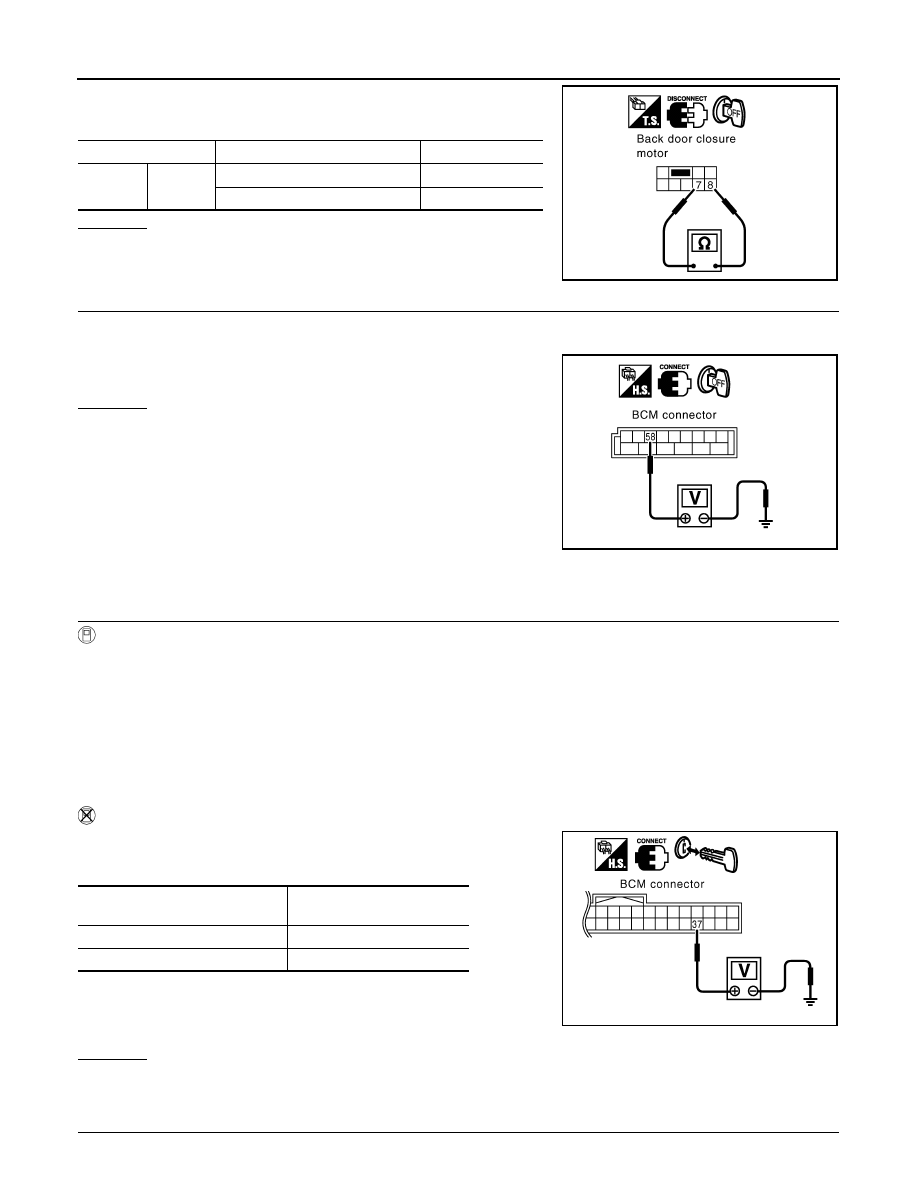
5.
CHECK BCM OUTPUT SIGNAL
1.
Connect BCM connector.
2.
Check voltage between BCM connector and ground.
OK or NG
OK
>> Check condition of harness and connector.
NG
>> Replace BCM.
Check Key Switch
INFOID:0000000001327826
1.
CHECK KEY SWITCH INPUT SIGNAL
With CONSULT-III
Check ignition key switch “KEY ON SW” in “DATA MONITOR” mode with CONSULT-III.
• When key is inserted in ignition key cylinder
• When key is removed from ignition key cylinder
Without CONSULT-III
Check voltage between BCM connector M3 terminal 37 (B/W) and
ground.
OK or NG
OK
>> Key switch circuit is OK.
NG
>> GO TO 2.
2.
CHECK KEY SWITCH
Terminals
Back door condition
Continuity
7
8
Open
Yes
Close
No
PIIA9934E
58 (L) – Ground
: Approx. 9V
PIIA6229E
KEY ON SW
: ON
KEY ON SW
: OFF
Condition of ignition key cylinder
Voltage (V)
Approx.
Key is inserted
Battery voltage
Key is removed
0
PIIA6471E
REMOTE KEYLESS ENTRY SYSTEM
BL-69
< SERVICE INFORMATION >
C
D
E
F
G
H
J
K
L
M
A
B
BL
N
O
P
1.
Disconnect key switch connector.
2.
Check continuity between key switch terminals 1 and 2.
OK or NG
OK
>>
Check the following.
• 15A fuse [No. 22, located in fuse block (J/B)]
• Harness for open or short between key switch and fuse
• Harness for open or short between BCM and key switch
NG
>> Replace key switch.
Check Remote Keyless Entry Receiver
INFOID:0000000001327827
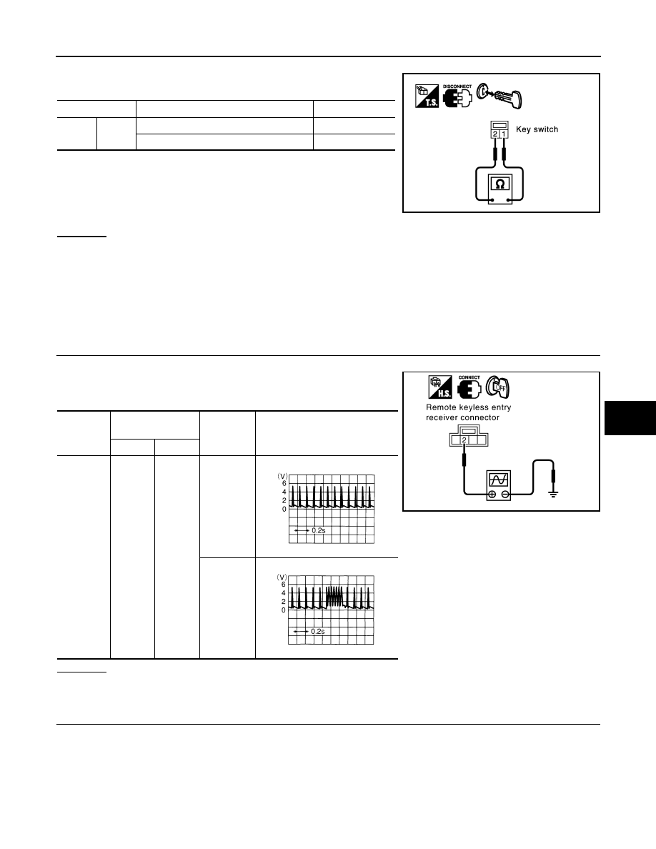
1.
CHECK REMOTE KEYLESS ENTRY RECEIVER OUTPUT SIGNAL
1.
Turn ignition switch OFF.
2.
Check remote keyless entry receiver connector M98 terminal 2
(L) and ground signal with oscilloscope.
OK or NG
OK
>> Remote keyless entry receiver circuit is OK.
NG
>> GO TO 2.
2.
CHECK REMOTE KEYLESS ENTRY RECEIVER INPUT VOLTAGE
1.
Disconnect remote keyless entry receiver connector.
2.
Check voltage between remote keyless entry receiver connector M98 terminal 4 (R) and ground.
Terminal
Key switch condition
Continuity
1
2
Key is inserted in IGN key cylinder.
Yes
Key is removed from IGN key cylinder
No
PIIA2627E
Connector
Terminal
(Wire color)
Condition
of keyfob
Voltage
(Reference value)
(+)
(–)
M98
2
Ground
No function
Any button
is pressed
PIIB1375E
OCC3879D
OCC3880D
BL-70
< SERVICE INFORMATION >
REMOTE KEYLESS ENTRY SYSTEM
OK or NG
OK
>> GO TO 4.
NG
>> GO TO 3.
3.
CHECK REMOTE KEYLESS ENTRY RECEIVER POWER SUPPLY CIRCUIT
1.
Disconnect BCM connector.
2.
Check continuity between remote keyless entry receiver connector M78 terminal 4 (R) and BCM connec-
tor M1 terminal 19 (R).
3.
Check continuity between remote keyless entry receiver connector M78 terminal 4 (R) and ground.
OK or NG
OK
>>
Check harness connection.
• If it is OK, replace BCM.
• If it is NG, repair or replace malfunction part.
NG
>> Repair or replace the harness.
4.
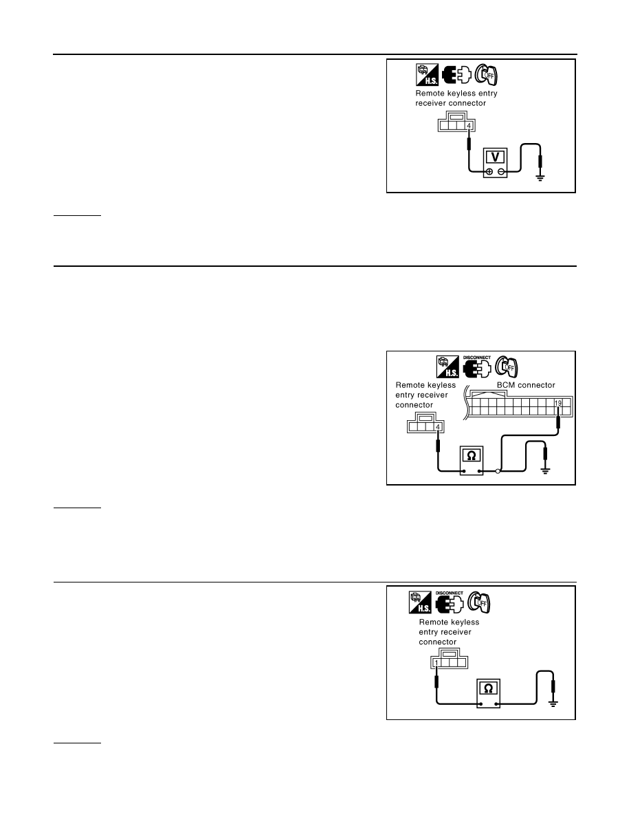
CHECK REMOTE KEYLESS ENTRY RECEIVER GROUND CIRCUIT
1.
Check continuity between remote keyless entry receiver con-
nector M78 terminal 1 (B) and ground.
OK or NG
OK
>> GO TO 6.
NG
>> GO TO 5.
4 (Y) – Ground
: Approx. 4.5V
PIIB3953E
4 (R) – 19 (R)
: Continuity should exist.
4 (R) – Ground
: Continuity should not exist.
PIIA9630E
1 (B) – Ground
: Continuity should exist.
PIIB1376E
Нет комментариевНе стесняйтесь поделиться с нами вашим ценным мнением.
Текст