Infiniti FX35 / FX45. Manual — part 776
TROUBLE DIAGNOSIS
LAN-81
< SERVICE INFORMATION >
[CAN]
C
D
E
F
G
H
I
J
L
M
A
B
LAN
N
O
P
CAN Communication Circuit
INFOID:0000000001328669
INSPECTION PROCEDURE
1.
CONNECTOR INSPECTION
1.
Turn the ignition switch OFF
2.
Disconnect the battery cable from the negative terminal.
3.
Disconnect all the unit connectors on CAN communication system.
4.
Check terminals and connectors for damage, bend and loose connection.
OK or NG
OK
>> GO TO 2.
NG
>> Repair the terminal and connector.
2.
CHECK HARNESS CONTINUITY (SHORT CIRCUIT)
Check the continuity between the data link connector terminals.
OK or NG
OK
>> GO TO 3.
NG
>> Check the harness and repair the root cause.
3.
CHECK HARNESS CONTINUITY (SHORT CIRCUIT)
Check the continuity between the data link connector and the ground.
OK or NG
OK
>> GO TO 4.
NG
>> Check the harness and repair the root cause.
4.
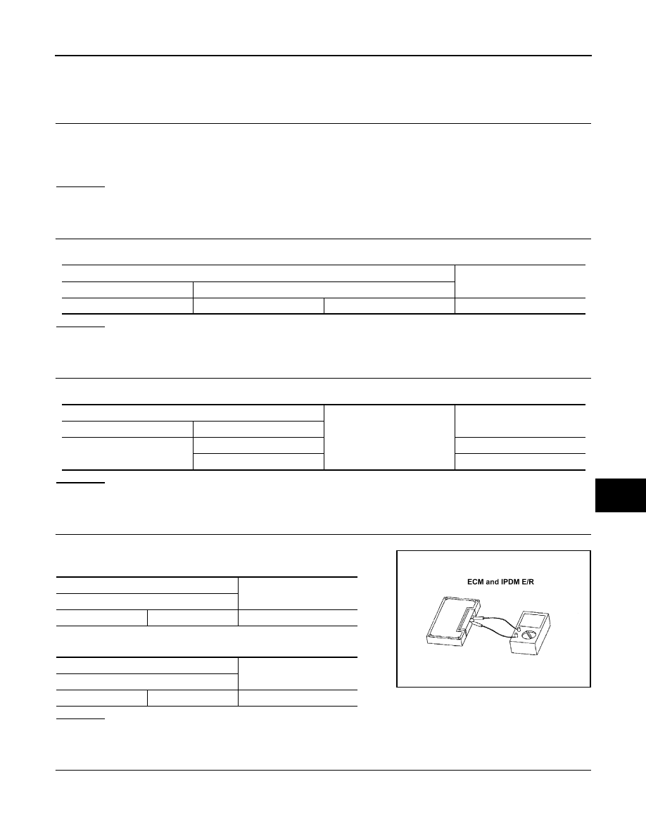
CHECK ECM AND IPDM E/R TERMINATION CIRCUIT
1.
Remove the ECM and the IPDM E/R.
2.
Check the resistance between the ECM terminals.
3.
Check the resistance between the IPDM E/R terminals.
OK or NG
OK
>> GO TO 5.
NG
>> Replace the ECM and/or the IPDM E/R.
5.
CHECK SYMPTOM
Connect all the connectors. Check if the symptoms described in the “Symptom (Results from interview with
customer)” are reproduced.
Data link connector
Continuity
Connector No.
Terminal No.
M5
6
14
No
Data link connector
Ground
Continuity
Connector No.
Terminal No.
M5
6
No
14
No
ECM
Resistance (
Ω
)
Terminal No.
94
86
Approx. 108 – 132
IPDM E/R
Resistance (
Ω
)
Terminal No.
48
49
Approx. 108 – 132
LKIA0037E
LAN-82
< SERVICE INFORMATION >
[CAN]
TROUBLE DIAGNOSIS
Inspection result
Reproduced>>GO TO 6.
Non-reproduced>>Start the diagnosis again. Follow the trouble diagnosis procedure when past error is
detected.
6.
CHECK UNIT REPRODUCTION
Perform the reproduction test as per the following procedure for each unit.
1.
Turn the ignition switch OFF
2.
Disconnect the battery cable from the negative terminal.
3.
Disconnect one of the unit connectors of CAN communication system.
NOTE:
ECM and IPDM E/R have a termination circuit. Check other units first.
4.
Connect the battery cable to the negative terminal. Check if the symptoms described in the “Symptom
(Results from interview with customer)” are reproduced.
NOTE:
Although unit-related error symptoms occur, do not confuse them with other symptoms.
Inspection result
Reproduced>>Connect the connector. Check other units as per the above procedure.
Non-reproduced>>Replace unit whose connector was disconnected.
LT-1
ELECTRICAL
C
D
E
F
G
H
I
J
L
M
SECTION
LT
A
B
LT
N
O
P
CONTENTS
LIGHTING SYSTEM
SERVICE INFORMATION . . . . . . .
PRECAUTIONS . . . . . . . . . . . . ...
General Precaution for Service Operation . . . ....
HEADLAMP - XENON TYPE - . . . . . . .
Component Parts and Harness Connector Loca-
tion . . . . . . . . . . . . . . . . . . ....
System Description . . . . . . . . . . . . ...
CAN Communication System Description . . . .....
CAN Communication Unit . . . . . . . . . .....
Schematic . . . . . . . . . . . . . . . .....
Wiring Diagram - H/LAMP - . . . . . . . . . ...
Terminal and Reference Value for BCM . . . . .
Terminal and Reference Value for IPDM E/R . . .
How to Proceed with Trouble Diagnosis . . . . .
Preliminary Check . . . . . . . . . . . . ...
CONSULT-III Functions (BCM) . . . . . . . ...
CONSULT-III Functions (IPDM E/R) . . . . . ...
Headlamp Does Not Change To High Beam (Both
Sides) . . . . . . . . . . . . . . . . . ..
Headlamp Does Not Change To High Beam (One
Side) . . . . . . . . . . . . . . . . . .
Headlamp Low Beam Does Not Illuminate (Both
Sides) . . . . . . . . . . . . . . . . . ..
Headlamp Low Beam Does Not Illuminate (One
Side) . . . . . . . . . . . . . . . . . .
Headlamp RH Low Beam and High Beam Does
Not Illuminate . . . . . . . . . . . . . . ..
Headlamp LH Low Beam and High Beam Does
Not Illuminate . . . . . . . . . . . . . . ..
Headlamps Does Not Turn OFF . . . . . . . .
General Information for Xenon Headlamp Trouble
Diagnosis . . . . . . . . . . . . . . . .
Caution: . . . . . . . . . . . . . . . . ...
Xenon Headlamp Trouble Diagnosis . . . . . ..
Aiming Adjustment . . . . . . . . . . . . ..
Bulb Replacement . . . . . . . . . . . . ...
Removal and Installation . . . . . . . . . . .
Disassembly and Assembly . . . . . . . . . .
DAYTIME LIGHT SYSTEM . . . . . . . ...
Component Parts and Harness Connector Loca-
tion . . . . . . . . . . . . . . . . . . ...
System Description . . . . . . . . . . . . ..
CAN Communication System Description . . . ...
CAN Communication Unit . . . . . . . . . .
Schematic . . . . . . . . . . . . . . . .
Wiring Diagram - DTRL - . . . . . . . . . . .
Terminal and Reference Value for BCM . . . . ..
How to Proceed with Trouble Diagnosis . . . . ..
Preliminary Check . . . . . . . . . . . . ...
CONSULT-III Functions (BCM) . . . . . . . ...
Daytime Light Control Does Not Operate Properly .
Aiming Adjustment . . . . . . . . . . . . ...
Bulb Replacement . . . . . . . . . . . . ...
Removal and Installation . . . . . . . . . . .
Disassembly and Assembly . . . . . . . . . .
AUTO LIGHT SYSTEM . . . . . . . . . .
Component Parts and Harness Connector Loca-
tion . . . . . . . . . . . . . . . . . . ...
System Description . . . . . . . . . . . . ..
CAN Communication System Description . . . ...
CAN Communication Unit . . . . . . . . . .
Major Component and Functions . . . . . . .
Schematic . . . . . . . . . . . . . . . .
Wiring Diagram - AUTO/L - . . . . . . . . . .
Terminal and Reference Value for BCM . . . . ..
Terminal and Reference Value for IPDM E/R . . ..
How to Proceed with Trouble Diagnosis . . . . ..
Preliminary Check . . . . . . . . . . . . ...
CONSULT-III Functions (BCM) . . . . . . . ...
CONSULT-III Functions (IPDM E/R) . . . . . ...
Symptom Chart . . . . . . . . . . . . . .
Lighting Switch Inspection . . . . . . . . . ...
Optical sensor System Inspection . . . . . . ...
LT-2
HEADLAMP AIMING CONTROL . . . . . ..
Schematic . . . . . . . . . . . . . . . ...
Wiring Diagram - H/AIM - . . . . . . . . . ...
Removal and Installation . . . . . . . . . ....
Switch Circuit Inspection . . . . . . . . . ....
FRONT FOG LAMP . . . . . . . . . . ...
Component Parts and Harness Connector Loca-
tion . . . . . . . . . . . . . . . . . . ..
System Description . . . . . . . . . . . . .
CAN Communication System Description . . . ..
CAN Communication Unit . . . . . . . . . ...
Wiring Diagram - F/FOG - . . . . . . . . . ..
Terminal and Reference Value for BCM . . . . .
Terminal and Reference Value for IPDM E/R . . .
How to Proceed with Trouble Diagnosis . . . . .
Preliminary Check . . . . . . . . . . . . ..
CONSULT-III Functions (BCM) . . . . . . . ..
CONSULT-III Functions (IPDM E/R) . . . . . ..
Front Fog Lamps Do Not Illuminate (Both Sides) ...
Front Fog Lamp Does Not Illuminate (One Side) ...
Aiming Adjustment . . . . . . . . . . . . ..
Bulb Replacement . . . . . . . . . . . . ..
Removal and Installation . . . . . . . . . ....
TURN SIGNAL AND HAZARD WARNING
LAMPS . . . . . . . . . . . . . . . ...
Component Parts and Harness Connector Loca-
tion . . . . . . . . . . . . . . . . . . ..
System Description . . . . . . . . . . . . .
CAN Communication System Description . . . ..
CAN Communication Unit . . . . . . . . . ...
Schematic . . . . . . . . . . . . . . . ...
Wiring Diagram - TURN - . . . . . . . . . ....
Terminal and Reference Value for BCM . . . . .
Terminal and Reference Value for Rear Combina-
tion Lamp Control Unit . . . . . . . . . . ....
How to Proceed with Trouble Diagnosis . . . . .
Preliminary Check . . . . . . . . . . . . ..
CONSULT-III Functions (BCM) . . . . . . . ..
Turn Signal Lamp Does Not Operate . . . . . .
Rear Turn Signal Lamp Does Not Operate . . ....
Hazard Warning Lamp Does Not Operate But
Turn Signal Lamp Operates . . . . . . . . ...
Bulb Replacement (Front Turn Signal Lamp) . . .
Bulb Replacement (Rear Turn Signal Lamp) . . ..
Removal and Installation of Front Turn Signal
Lamp . . . . . . . . . . . . . . . . . ...
Removal and Installation of Rear Turn Signal
Lamp . . . . . . . . . . . . . . . . . ...
Removal and Installation of Rear Combination
Lamp Control Unit . . . . . . . . . . . . ...
LIGHTING AND TURN SIGNAL SWITCH . . .
Removal and Installation . . . . . . . . . ....
HAZARD SWITCH . . . . . . . . . . . .
Removal and Installation . . . . . . . . . ....
COMBINATION SWITCH . . . . . . . . ..
Wiring Diagram - COMBSW - . . . . . . . . .
Combination Switch Reading Function . . . . ...
Terminal and Reference Value for BCM . . . . .
CONSULT-III Functions (BCM) . . . . . . . .
Combination Switch Inspection . . . . . . . .
Removal and Installation . . . . . . . . . ...
STOP LAMP . . . . . . . . . . . . . .
Component Parts and Harness Connector Loca-
tion . . . . . . . . . . . . . . . . . .
System Description . . . . . . . . . . . ...
Schematic . . . . . . . . . . . . . . . .
Wiring Diagram - STOP/L - . . . . . . . . ...
Terminal and Reference Value for Rear Combina-
tion Lamp Control Unit . . . . . . . . . . ..
Stop Lamp Does Not Operate . . . . . . . ...
High-Mounted Stop Lamp . . . . . . . . . .
Stop Lamp . . . . . . . . . . . . . . . .
Rear Combination Lamp Control Unit . . . . ...
BACK-UP LAMP . . . . . . . . . . . ..
Wiring Diagram - BACK/L - . . . . . . . . ...
Bulb Replacement . . . . . . . . . . . . .
Removal and Installation . . . . . . . . . ...
PARKING, LICENSE PLATE AND TAIL
LAMPS . . . . . . . . . . . . . . . ..
Component Parts and Harness Connector Loca-
tion . . . . . . . . . . . . . . . . . .
System Description . . . . . . . . . . . ...
CAN Communication System Description . . .
CAN Communication Unit . . . . . . . . . .
Schematic . . . . . . . . . . . . . . . .
Wiring Diagram - TAIL/L - . . . . . . . . . .
Terminal and Reference Value for BCM . . . ...
Terminal and Reference Value for IPDM E/R . ...
Terminal and Reference Value for Rear Combina-
tion Lamp Control Unit . . . . . . . . . . ..
How to Proceed with Trouble Diagnosis . . . ...
Preliminary Check . . . . . . . . . . . . .
CONSULT-III Functions (BCM) . . . . . . . .
CONSULT-III Functions (IPDM E/R) . . . . . .
Parking, License Plate and Side Marker Lamps
Do Not Illuminate . . . . . . . . . . . . ..
Tail Lamp Does Not Operate . . . . . . . .
License Plate Lamp . . . . . . . . . . . ..
Front Parking Lamp . . . . . . . . . . . ..
Tail Lamp . . . . . . . . . . . . . . . ..
Front Side Marker Lamp . . . . . . . . . ...
Rear Side Marker Lamp . . . . . . . . . .
Rear Combination Lamp Control Unit . . . . ...
REAR COMBINATION LAMP . . . . . . ..
Bulb Replacement . . . . . . . . . . . . .
Removal and Installation . . . . . . . . . ...
Нет комментариевНе стесняйтесь поделиться с нами вашим ценным мнением.
Текст