Infiniti FX35 / FX45. Manual — part 167
AV-122
< SERVICE INFORMATION >
NAVIGATION SYSTEM
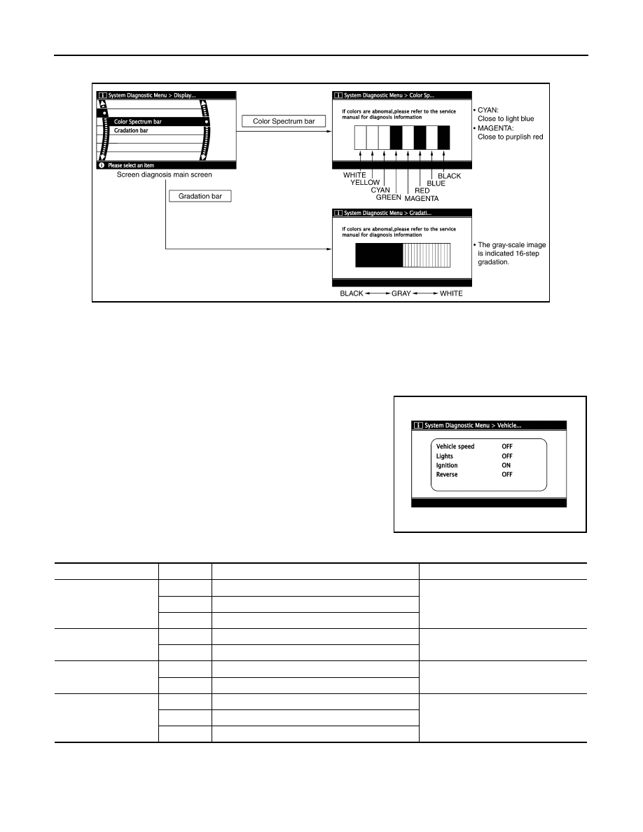
Color tone and shading of the NAVI control unit-generated image can be checked by the display of a color bar
and a gray scale.
• If RGB signal is malfunctioning, the tint of the color bar display is as follows.
Vehicle Signals
A comparison check can be made of each actual vehicle signal and
the signals recognized by the NAVI control unit.
Navigation
Steering Angle Adjustment
R (red) signal error
: Light blue (Cyan) tint
G (green) signal error
: Purple (Magenta) tint
B (blue) signal error
: Yellow tint
SKIB6976E
SKIB6977E
Diagnosis item
Display
Condition
Remarks
Vehicle speed
ON
When vehicle speed is more than 0 km/h (0 MPH)
Changes in indication may be delayed.
This is normal.
OFF
When vehicle speed is 0 km/h (0 MPH)
—
Ignition switch in ACC position
Lights
ON
Lighting switch ON
—
OFF
Lighting switch OFF
Ignition
ON
Ignition switch ON
—
OFF
Ignition switch ACC position
Reverse
ON
Selector lever in R position
Changes in indication may be delayed.
This is normal.
OFF
Selector lever in any position other than R position
—
Ignition switch in ACC position
NAVIGATION SYSTEM
AV-123
< SERVICE INFORMATION >
C
D
E
F
G
H
I
J
L
M
A
B
AV
N
O
P
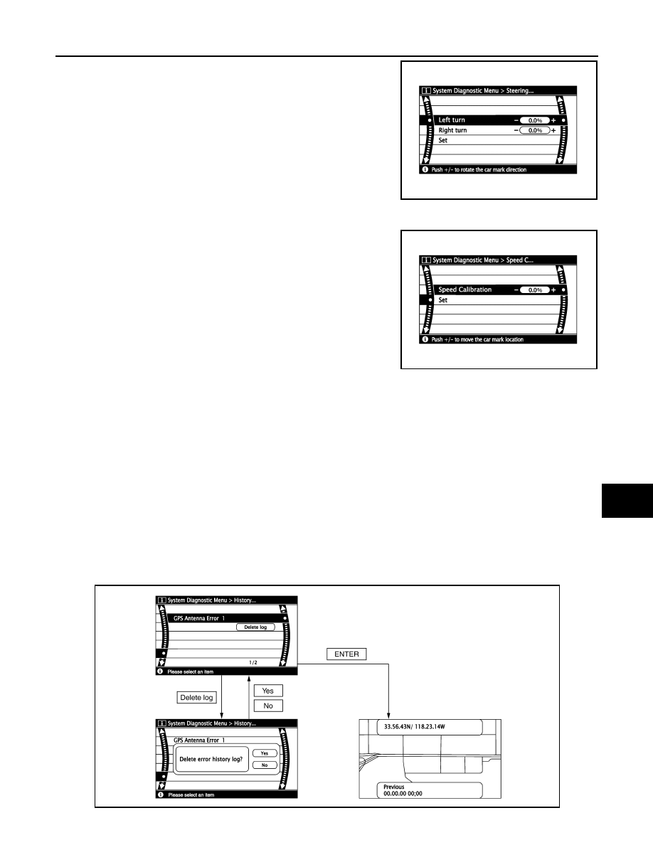
The steering angle output value detected by the gyroscope can be
adjusted.
Speed Calibration
Usually the automatic distance correction function adjusts the mal-
function in distance caused by the tires wearing down or the tire
pressure change. If prompt adjustment is necessary when the tire
chains are installed, etc., perform this procedure.
Error History
Diagnosis results of self-diagnosis depend on if any error occurred during the time after selecting “Self Diag-
nosis” until self-diagnosis results is displayed.
Meanwhile, when an error occurs before selecting “Self Diagnosis”, and if an error does not occur until self-
diagnosis results is displayed, a diagnosis result is judged as normal.
Consequently, a diagnosis needs to be performed with “Error History” for the past error that is not available
with self-diagnosis.
“Error History” displays the time and place of the most recent occurrence of that error. However, take note of
the following points.
• Correct time of the error occurrence may not be displayed when the GPS antenna substrate within the NAVI
control unit has malfunctioned.
• Place of the error occurrence is represented by the position of the vehicle mark at the time when the error
occurred. If the vehicle mark has deviated from the correct position, then the place of the error occurrence
may not be located correctly.
• When the ignition switch is turned ON if the error is detected, the counter increases 1. Even if it is normal
when the ignition switch is turned ON the next time, the counter does not decrease.
• The upper limit of the counter is 50. 51 or more is displayed as 50. It can be reset to 0 by “Delete log” switch.
SKIB3684E
SKIB3685E
SKIB6978E

AV-124
< SERVICE INFORMATION >
NAVIGATION SYSTEM
Diagnosis by Error History
• When having a difficulty on the investigation of cause due to multiple errors with a reproducible malfunction,
turn ON the ignition switch from OFF mode after making a memo of the item and number of time (or delete
“Error History”). Check “Error History” again after the malfunction was reproduced, and then perform diagno-
sis focusing on the item of which number of time increased.
• DVD-ROM error history may be restored because DVD-ROM cannot be temporarily read. (Driving on rough
road etc.) Then, erase the error history. (This is not a malfunction.) Perform service in “Action to take” if error
history are repeatedly indicated again.
Delete Unit Connection Log
Error item
Possible cause
Action to take
GPS Antenna Error
GPS antenna connection malfunction
is detected.
1.
Start self-diagnosis, and make sure
of the result.
2.
If any error is found, GO TO 3. If any
error is not found, delete the error
history and end the diagnosis. (This
is not a malfunction.)
3.
Check if GPS antenna feeder line is
snapped or pinched.
4.
If the results from the above checkup
show no malfunction, replace GPS
antenna, and then restart self-diag-
nosis.
5.
If self-diagnosis results still show any
malfunction, replace NAVI control
unit.
FLASH-ROM Error Of Control Unit
NAVI control unit malfunction is detect-
ed.
1.
Start self-diagnosis, and make sure
of the result.
2.
If any error is found, replace NAVI
control unit. Refer to
moval and Installation of NAVI Con-
trol Unit"
. If any error is not found,
delete the error history and end the
diagnosis. (This is not a malfunc-
tion.)
Connection Of Gyro
GPS Communication Error
GPS malfunction is detected.
If the symptoms such as the GPS receipt
malfunction occur, intermittent malfunc-
tion caused by strong radio interference
may be detected.
If the malfunction always occurs, replace
NAVI control unit.
GPS ROM Error
GPS RAM Error
GPS RTC Error
DVD-ROM Mechanism not Detected
• Malfunction is detected on DVD-
ROM drive pickup lens in NAVI con-
trol unit.
• There is dirt and damage on the
DVD-ROM.
1.
Check if the inserted DVD-ROM is
specified for this navigation system,
and the DVD-ROM is dirty, scratched
or warped.
2.
If the results from the above checkup
show no malfunction, insert the
same DVD-ROM, and then restart
self-diagnosis.
3.
If self-diagnosis results still show any
malfunction, replace NAVI control
unit.
DVD-ROM Communication Error
DVD-ROM Mechanism Error
DVD-ROM Focus Error
DVD-ROM TOC Error
DVD-ROM Disc Error
DVD-ROM Seek Error
DVD-ROM Error Correction Error
DVD-ROM Read Error
DVD-ROM Data Transfer Error
DVD-ROM Data Error
DVD-ROM Loading / Eject Error
DVD-ROM Time-out
NAVIGATION SYSTEM
AV-125
< SERVICE INFORMATION >
C
D
E
F
G
H
I
J
L
M
A
B
AV
N
O
P
Erase the connection history of unit and error history that is recorded
in NAVI control unit (clear the connection history of the removed
unit).
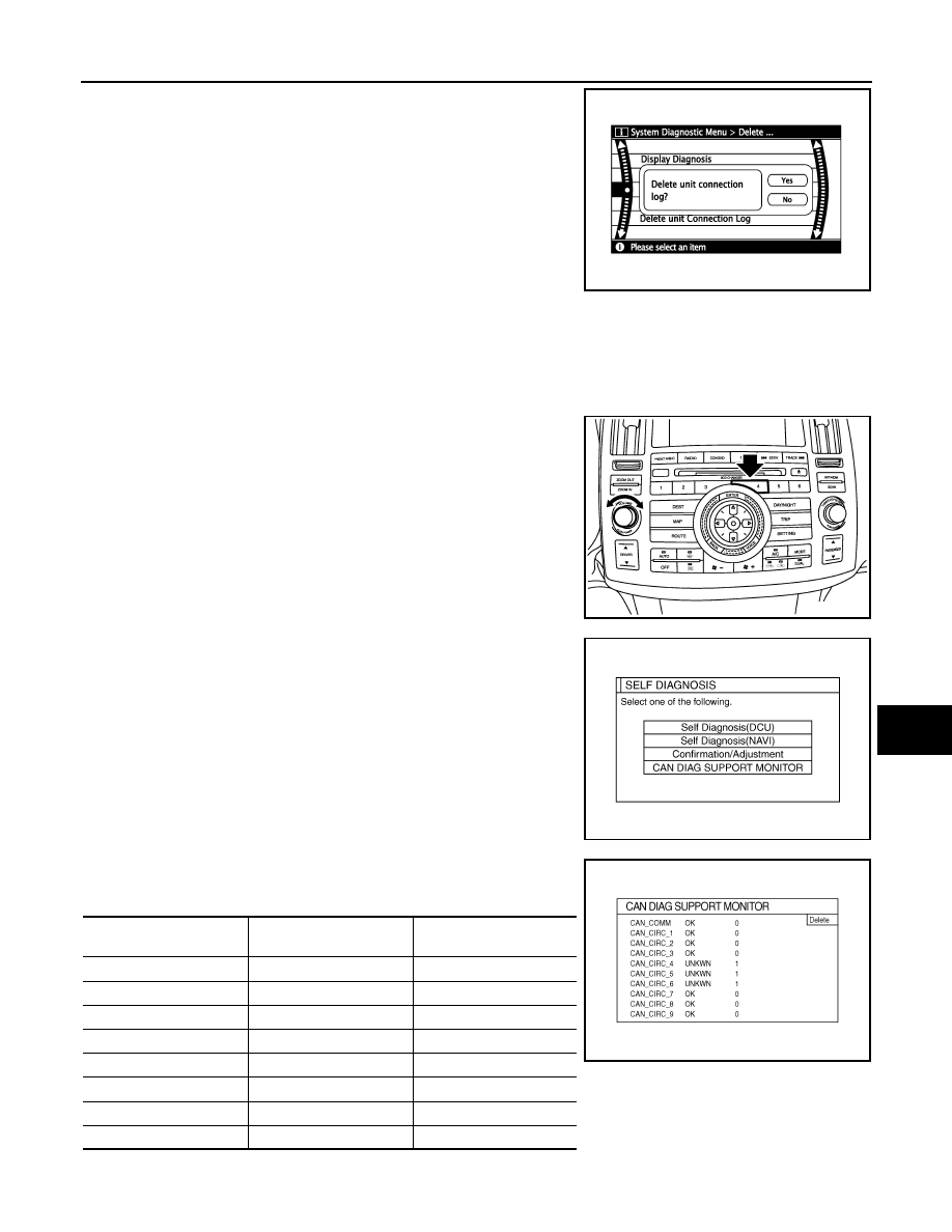
CAN Diagnostic Support Monitor
INFOID:0000000001328756
OPERATION PROCEDURE
1.
Start the engine.
2.
Turn the audio system OFF.
3.
While pressing the “4” button, turn the volume control dial clock-
wise or counterclockwise for 30 clicks or more. (When the self-
diagnosis mode is started, a short beep will be heard.)
• Shifting from current screen to previous screen is performed
by pressing “BACK” button.
4.
The initial trouble diagnosis screen will be shown, and items
“Self Diagnosis (DCU)”, “Self Diagnosis (NAVI)”, “Confirmation/
Adjustment” and “CAN DIAG SUPPORT MONITOR” will
become selective.
5.
Select “CAN DIAG SUPPORT MONITOR”.
6.
The transmitting/receiving of CAN communication can be moni-
tored.
SKIB6979E
SKIB8642E
SKIB7874E
Item
Content
Error counter
(Reference value)
CAN_COMM
OK/NG
0 - 50
CAN_CIRC_1
OK/UNKWN
0 - 50
CAN_CIRC_2
OK/UNKWN
0 - 50
CAN_CIRC_3
OK/UNKWN
0 - 50
CAN_CIRC_4
OK/UNKWN
0 - 50
CAN_CIRC_5
OK/UNKWN
0 - 50
CAN_CIRC_6
OK/UNKWN
0 - 50
CAN_CIRC_7
OK/UNKWN
0 - 50
SKIA4288E
Нет комментариевНе стесняйтесь поделиться с нами вашим ценным мнением.
Текст